INSTALLATION
Installing Blower Assembly - GA3450T (Cont.)
11
INSTALLATION
Continued
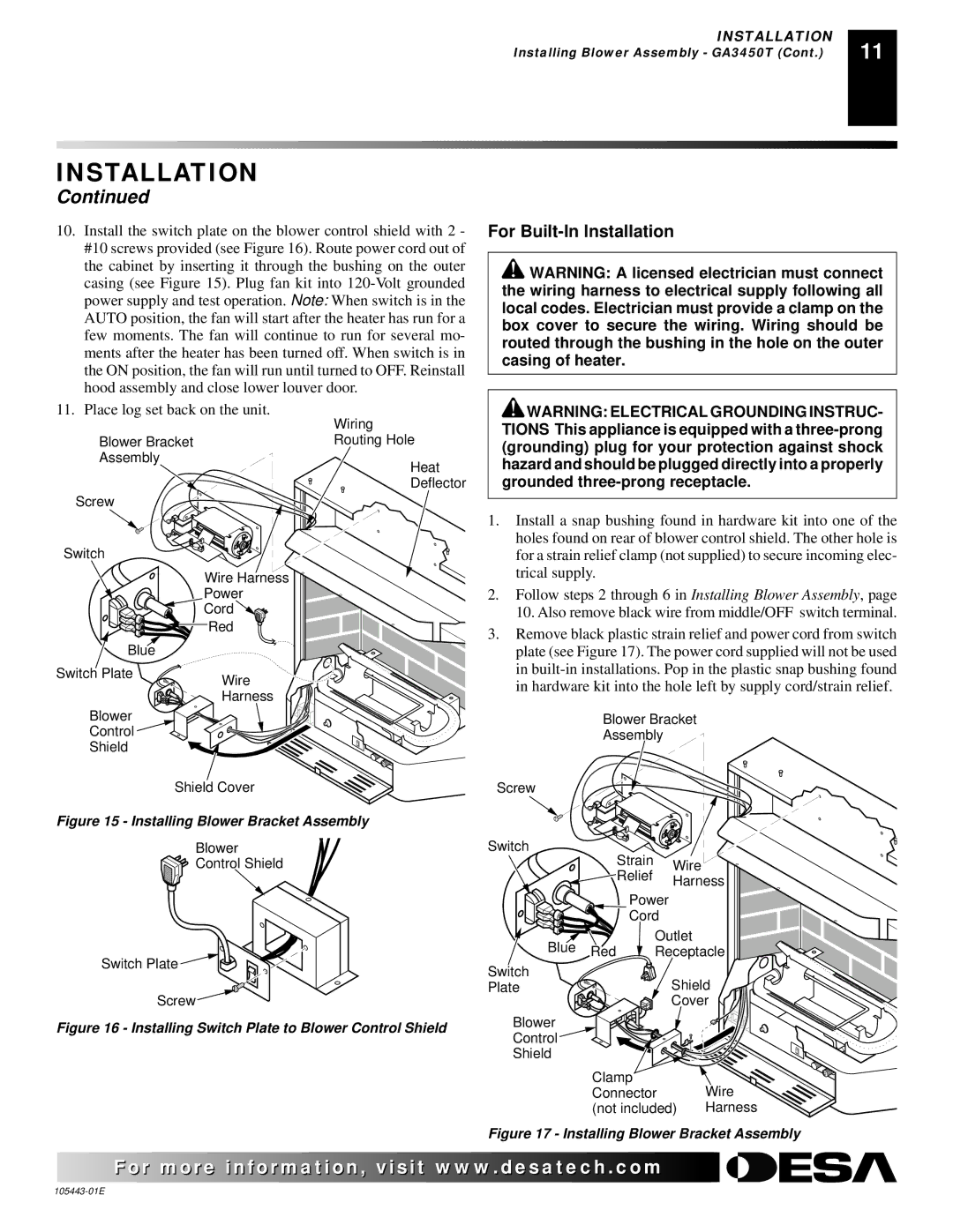
10.Install the switch plate on the blower control shield with 2 - #10 screws provided (see Figure 16). Route power cord out of the cabinet by inserting it through the bushing on the outer casing (see Figure 15). Plug fan kit into
For Built-In Installation
![]() WARNING: A licensed electrician must connect the wiring harness to electrical supply following all local codes. Electrician must provide a clamp on the box cover to secure the wiring. Wiring should be routed through the bushing in the hole on the outer casing of heater.
WARNING: A licensed electrician must connect the wiring harness to electrical supply following all local codes. Electrician must provide a clamp on the box cover to secure the wiring. Wiring should be routed through the bushing in the hole on the outer casing of heater.
11. Place log set back on the unit.
Blower Bracket
Assembly
Screw
Switch
| Wire Harness |
| Power |
| Cord |
| Red |
Blue |
|
Switch Plate | Wire |
| |
| Harness |
Blower |
|
Control |
|
Shield |
|
| Shield Cover |
Wiring
Routing Hole
Heat
Deflector
![]() WARNING: ELECTRICAL GROUNDING INSTRUC- TIONS This appliance is equipped with a
WARNING: ELECTRICAL GROUNDING INSTRUC- TIONS This appliance is equipped with a
1.Install a snap bushing found in hardware kit into one of the holes found on rear of blower control shield. The other hole is for a strain relief clamp (not supplied) to secure incoming elec- trical supply.
2.Follow steps 2 through 6 in Installing Blower Assembly, page 10. Also remove black wire from middle/OFF switch terminal.
3.Remove black plastic strain relief and power cord from switch plate (see Figure 17). The power cord supplied will not be used in
Blower Bracket
Assembly
Screw
Figure 15 - Installing Blower Bracket Assembly
Blower
![]()
![]() Control Shield
Control Shield
Switch Plate ![]()
Screw ![]()
Figure 16 - Installing Switch Plate to Blower Control Shield
Switch |
| Strain |
|
| |
|
| Wire |
| ||
|
| Relief |
| ||
|
| Harness | |||
|
|
| |||
|
| Power |
|
| |
|
| Cord |
|
| |
Blue | Red | Outlet |
| ||
Receptacle | |||||
| |||||
Switch |
|
| Shield | ||
Plate |
|
| |||
|
|
| Cover | ||
Blower |
|
|
|
| |
Control |
|
|
|
| |
Shield |
|
|
|
| |
| Clamp |
| Wire | ||
| Connector |
| |||
| (not included) | Harness | |||
Figure 17 - Installing Blower Bracket Assembly
![]() For more
For more![]()
![]()
![]() visit www.
visit www.![]()
![]()
![]() .com
.com![]()
![]()
![]()
![]()
![]()
![]()