DVF32TMHST specifications
The Desa DVF32TMHST is a sophisticated vent-free gas fireplace that stands out for its combination of elegance, efficiency, and advanced technology. Designed to provide warmth and comfort, this unit offers a reliable heating solution for both modern and traditional spaces.One of the standout features of the DVF32TMHST is its impressive heating capacity, capable of warming areas up to 1,200 square feet. This makes it an ideal choice for living rooms, open-concept spaces, or any area where consistent warmth is desired. The unit utilizes propane or natural gas, making it versatile for various home setups while ensuring operational efficiency.
A notable characteristic of the DVF32TMHST is its vent-free technology. This means it does not require traditional flue or venting systems, allowing for flexible installation and minimizing structural modifications. The vent-free design also contributes to optimal heat retention, ensuring that more warmth stays within the room rather than being lost through a chimney.
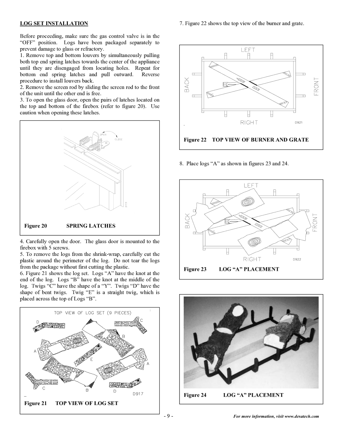
The DVF32TMHST is equipped with an advanced burner system that simulates realistic flames, providing a captivating visual that enhances any room's atmosphere. The realism of the flames is paired with a variety of decorative media options, such as ceramic logs and glowing embers, allowing homeowners to customize the appearance to suit their taste.
Furthermore, the unit incorporates safety features such as an oxygen depletion sensor (ODS), which automatically shuts off the fireplace if oxygen levels fall below a safe threshold. This provides peace of mind for users, making it a safe choice for any living area.
Efficiency is paramount in the design of the DVF32TMHST, boasting an impressive 99% efficiency rating which translates to lower heating costs for homeowners. Additionally, the fireplace operates silently, ensuring that the ambiance of any gathering remains uninterrupted while providing warmth.
In summary, the Desa DVF32TMHST vent-free gas fireplace combines stylish design with cutting-edge technology and features, making it a remarkable heating solution for any home. Its ability to provide substantial heat without the need for venting, coupled with advanced safety features and customizable aesthetics, makes it a worthy addition for those seeking comfort and elegance in their living spaces.

