Manuals
/
Desa
/
Household Appliance
/
Electric Heater
Desa
GCP6 GCN10T, GCP20T Attaching Thermostat Sensing Bulb, Marking Screw Locations, Installation
Models:
GCP6 GCN10T
GCN6
GCP10TGCN20T
GCP20T
1
8
60
60
Download
60 pages
7.16 Kb
5
6
7
8
9
10
11
12
Troubleshooting
Specifications
Install
Parts list
Connecting To Gas Supply
Warranty
Maintenance
Observed Problem
Accessoires
Manual Lighting Procedure
Page 8
Image 8
Page 7
Page 9
Page 8
Image 8
Page 7
Page 9
Contents
GCN20T, GCP20T
GCN6, GCP6
WHAT TO DO IF YOU SMELL GAS
Do not try to light any appliance
WARNINGS
TABLE OF CONTENTS
SAFETY INFORMATION
PRODUCT FEATURES
SAFETY DEVICE
UNPACKING
PRODUCT IDENTIFICATION
LOCAL CODES
AIR FOR COMBUSTION AND VENTILATION
PROVIDING ADEQUATE VENTILATION
Unusually Tight Construction
DETERMINING FRESH-AIRFLOW FOR HEATER LOCATION
AIR FOR COMBUSTION AND VENTILATION
Continued
AIR FOR COMBUSTION AND VENTILATION
INSTALLATION
VENTILATION AIR
CHECK GAS TYPE
Ventilation Air From Inside Building
INSTALLATION ITEMS
LOCATING HEATER
INSTALLATION
Continued
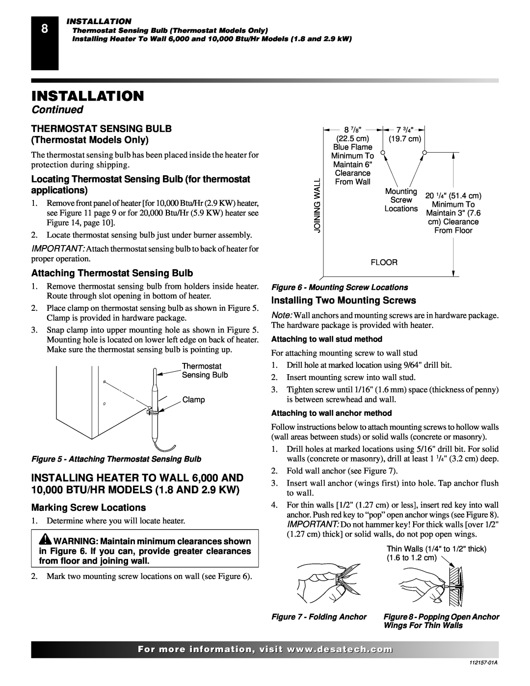
Installing Two Mounting Screws
Attaching Thermostat Sensing Bulb
Marking Screw Locations
THERMOSTAT SENSING BULB Thermostat Models Only
Installing Bottom Mounting Screw
Placing Heater On Mounting Screws
Removing Front Panel Of Heater
Mounting Bracket
Methods For Attaching Mounting Bracket To Wall
Attaching Mounting Bracket To Wall
INSTALLATION
Continued
Installing Bottom Mounting Screws
Placing Heater On Mounting Bracket
Mounting Base Feet to Heater
INSTALLATION
CONNECTING TO GAS SUPPLY
INSTALLATION
INSTALLATION
Continued
Pressure Testing Gas Supply Piping System
Pressure Testing Heater Gas Connections
CHECKING GAS CONNECTIONS
INSTALLATION
LIGHTING INSTRUCTIONS
FOR YOUR SAFETY READ BEFORE LIGHTING
OPERATING HEATER
MANUAL LIGHTING PROCEDURE
INSPECTING BURNER
TO TURN OFF GAS TO APPLIANCE
THERMOSTAT CONTROL OPERATION THERMOSTAT
CLEANING AND MAINTENANCE
CABINET
ODS/PILOT AND BURNER ORIFICE
BURNER PILOT AIR INLET HOLE
TROUBLESHOOTING
OBSERVED PROBLEM
POSSIBLE CAUSE
REMEDY
Maintenance, page
TROUBLESHOOTING
OBSERVED PROBLEM
Continued
ing Gas Connections, page
1. Refer to Fresh Air for Combustion and
TROUBLESHOOTING
OBSERVED PROBLEM
ILLUSTRATED PARTS BREAKDOWN
MANUAL CONTROL MODELS GCP6 AND GCN6
PILOT
ILLUSTRATED PARTS BREAKDOWN
PARTS LIST
PARTS LIST
PART NUMBER
GCP6
THERMOSTAT CONTROLLED MODELS
GCP10T GCN10T
ILLUSTRATED PARTS BREAKDOWN
PILOT
PARTS LIST
PARTS LIST
PART NUMBER
GCP10T
THERMOSTAT CONTROLLED
MODELS
GCN20T AND GCP20T
ILLUSTRATED PARTS BREAKDOWN
PARTS LIST
PARTS LIST
PART NUMBER
GCN20T
SPECIFICATIONS
SERVICE CENTER/PARTS CENTRAL
GCP6
GCP10T
OWNERS REGISTRATION FORM
Postage Required
TAPE
2701 Industrial Drive P.O. Box Bowling Green, KY
TAPE
REPLACEMENT PARTS
SERVICE PUBLICATIONS
ACCESSORIES
SERVICE HINTS
WARRANTY INFORMATION
LIMITED WARRANTY VENT-FREERESIDENTIAL GAS HEATERS
email desacan@sympatico.ca
Model Serial No Date Purchased
RADIATEUR À GAZ À FLAMME BLEUE SANS CONDUIT
D’ÉVACUATION
INFORMATIONS RELATIVES À LA SÉCURITÉ
ET MODE D’EMPLOI
AVERTISSEMENTS
TABLE DES MATIÈRES
INFORMATIONS RELATIVES À LA SÉCURITÉ
DÉBALLAGE
IDENTIFICATION DU PRODUIT
CARACTÉRISTIQUES DU PRODUIT
Suite
CODES LOCAUX
AIR POUR LA COMBUSTION ET LA VENTILATION
POUR FOURNIR UNE VENTILATION ADÉ QUATE
Construction particuliè rement é tanche
que l’espace peut supporter OU
AIR POUR LA COMBUSTION ET LA VENTILATION
Suite
AIR DE VENTILATION
VÉ RIFIEZ LE TYPE DE GAZ
Air de ventilation de l’inté rieur du bâ timent
Air de ventilation de l’exté rieur
ARTICLES POUR L’INSTALLATION
PLACEMENT DU RADIATEUR
INSTALLATION
AVERTISSEMENT Ne jamais installer le radiateur
Marquage de l’emplacement des vis
Installation des deux vis de montage
BULBE THERMOSTATIQUE
modè les à thermostat uniquement
Placement du radiateur sur les vis de montage
Installation de la vis de montage infé rieure
Retrait du panneau avant du radiateur
Support de montage
Fixation du support de montage au mur
INSTALLATION
Marquage de l’emplacement des vis
Suite
Placement du radiateur sur le support de montage
Installation des vis de montage infé rieures
Montage des pieds sur le radiateur
Montage des pieds au sol si le code local l’exige
Suite
RACCORDEMENT À L’ALIMENTATION EN GAZ
INSTALLATION
Suite
VÉ RIFICATION DES CONNEXIONS AU GAZ
INSTALLATION
INSTRUCTIONS D’ ALLUMAGE
UTILISATION DU RADIATEUR
POUR VOTRE SÉ CURITÉ - À LIRE AVANT L’ALLUMAGE
INSPECTION DU BRÛLEUR
POUR COUPER LE GAZ DE L’APPAREIL
UTILISATION DU CONTRÔ LE
PAR THERMOSTAT MODÈ LES À THERMOSTAT UNIQUEMENT
NETTOYAGE ET ENTRETIEN
ODS/VEILLEUSE ET ORIFICE DU BRÛ LEUR
HABILLAGE
Conduits d’air
SOLUTION
DÉPANNAGE
SYMPTÔ ME
CAUSE POSSIBLE
SOLUTION
DÉPANNAGE
Suite
SYMPTÔ ME
SOLUTION
DÉPANNAGE
Suite
SYMPTÔ ME
VUE DÉTAILLÉE DU RADIATEUR
MODÈ LES À CONTRÔ LE MANUEL GCP6 ET GCN6
VEILLEUSE
VUE DÉTAILLÉE DU RADIATEUR
LISTE DES PIÈCES
LISTE DES PIÈCES
NUMÉ RO DE PIÈ CE
GCP6
MODÈ LES CONTRÔ LÉ S PAR THERMOSTAT
GCP10T ET GCN10T
VUE DÉTAILLÉE DU RADIATEUR
VEILLEUSE
LISTE DES PIÈCES
LISTE DES PIÈCES
NUMÉ RO DE PIÈ CE
GCP10T
MODÈ LES CONTRÔ LÉ S PAR
THERMOSTAT
GCN20T ET GCP210T
VUE DÉTAILLÉE DU RADIATEUR
LISTE DES PIÈCES
LISTE DES PIÈCES
NUMÉ RO DE PIÈ CE
GCN20T
CENTRE DE SERVICE/DÉPÔT DE PIÈCES
SPÉCIFICATIONS
Page
Affran chissement Requis
RUBAN
RUBAN
2701 Industrial Drive P.O. Box Bowling Green, KY
PUBLICATIONS POUR LE SERVICE
ACCESSOIRES
CONSEILS DE SERVICE
SERVICE TECHNIQUE
INFORMATION SUR LA GARANTIE
GARANTIE LIMITÉE
NOT A UPC
2220, Argentia Road, Unité 4 Mississauga, Ontario
Top
Page
Image
Contents