6
SELECTING LOCATION
Clearances
SELECTING LOCATION
To determine the safest and most efficient location for your appli- ance, you must take into consideration the following guidelines:
1.The location must allow for proper clearances (see Clearances, next column).
2.Consider a location where heat output would not be affected by drafts, air conditioning ducts, windows, or doors.
3.A location that avoids the cutting of joists or roof rafters will make installation easier. Figure 2 shows a plan view of a few common locations.
Flush installations are recommended where living space is limited or at a premium, and since the space required to enclose the appliance would be located beyond an outside wall, this would also reduce the cutting of joists, roof rafters, and such. Check local codes for any restrictions.
PRE-INSTALLATION
PREPARATION
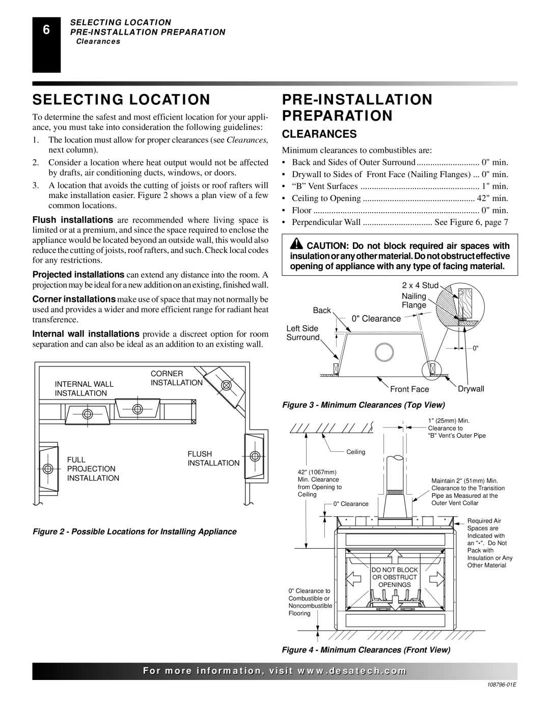
CLEARANCES
Minimum clearances to combustibles are: |
| |
• | Back and Sides of Outer Surround | 0" min. |
• | Drywall to Sides of Front Face (Nailing Flanges) ... 0" min. | |
• | “B” Vent Surfaces | 1" min. |
• | Ceiling to Opening | 42" min. |
• | Floor | 0" min. |
• | Perpendicular Wall | See Figure 6, page 7 |
![]() CAUTION: Do not block required air spaces with insulation or any other material. Do not obstruct effective opening of appliance with any type of facing material.
CAUTION: Do not block required air spaces with insulation or any other material. Do not obstruct effective opening of appliance with any type of facing material.
Projected installations can extend any distance into the room. A projection may be ideal for a new addition on an existing, finished wall.
Corner installations make use of space that may not normally be used and provides a wider and more efficient range for radiant heat
Back
2 x 4 Stud
Nailing
Flange
transference.
Internal wall installations provide a discreet option for room separation and can also be ideal as an addition to an existing wall.
0" Clearance 
Left Side
Surround
0"
| CORNER |
|
|
|
|
|
INTERNAL WALL | INSTALLATION |
|
| Front Face |
| Drywall |
INSTALLATION |
|
|
|
| ||
|
|
|
|
|
| |
|
| Figure 3 - Minimum Clearances (Top View) |
| |||
|
|
|
| 1" (25mm) Min. | ||
|
|
|
| Clearance to | ||
|
|
|
| "B" Vent’s Outer Pipe | ||
FULL | FLUSH | Ceiling |
|
|
|
|
INSTALLATION |
|
|
|
|
| |
PROJECTION |
|
|
|
|
| |
| 42" (1067mm) |
|
|
|
| |
INSTALLATION |
|
|
|
|
| |
| Min. Clearance |
|
| Maintain 2" (51mm) Min. | ||
|
| from Opening to |
|
| Clearance to the Transition | |
|
| Ceiling |
|
| Pipe as Measured at the | |
|
| 0" Clearance |
|
| Outer Vent Collar | |
|
| * | * | * | * | Required Air |
Figure 2 - Possible Locations for Installing Appliance |
|
|
|
| Spaces are | |
|
|
|
| Indicated with | ||
|
|
|
|
|
| |
|
|
|
|
|
| an "*". Do Not |
|
|
|
|
|
| Pack with |
|
|
|
|
|
| Insulation or Any |
|
|
| DO NOT BLOCK |
| Other Material | |
|
|
|
|
| ||
|
|
| OR OBSTRUCT |
|
| |
|
| 0" Clearance to |
| OPENINGS |
|
|
|
|
|
|
|
| |
|
| Combustible or |
|
|
|
|
|
| Noncombustible |
|
|
|
|
|
| Flooring |
|
|
|
|
Figure 4 - Minimum Clearances (Front View)
![]()
![]()
![]()
![]()
![]()
![]()
![]() For more
For more![]()
![]()
![]()
![]()
![]() visit www.
visit www.![]()
![]()
![]() .com
.com![]()
![]()
![]()
![]()
![]()
![]()
![]()