6
Clearances
Mantel Clearances and Wall Details
PRE-INSTALLATION
PREPARATION
CLEARANCES
Minimum clearances to combustibles are: |
| |
• | Top of Spacers | 0" min. |
• | Back and Sides of Outer Surround | 0" min. |
• | Drywall to Sides of Front Face (Nailing Flanges) ... 0" min. | |
• | “B” Vent Surfaces | 1" min. |
• | Ceiling to Opening | 42" min. |
• | Floor | 0" min. |
• | Perpendicular Wall | See Figure 6 |
![]() CAUTION: Do not block required air spaces with insulation or any other material. Do not obstruct effective opening of appliance with any type of facing material.
CAUTION: Do not block required air spaces with insulation or any other material. Do not obstruct effective opening of appliance with any type of facing material.
2 x 4 Stud
Nailing
BackFlange
0" Clearance ![]()
Left Side
Surround
0"
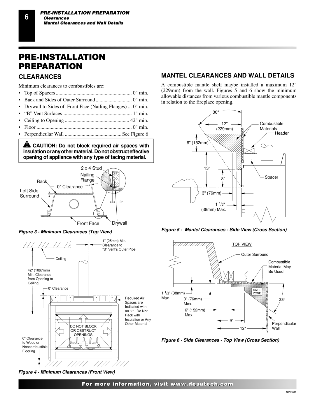
MANTEL CLEARANCES AND WALL DETAILS
A combustible mantle shelf maybe installed a maximum 12" (229mm) from the wall. Figures 5 and 6 show the minimum allowable distances from various combustible mantle components in relation to the fireplace opening.
12" | Combustible |
(229mm) | Materials |
Header
6" (152mm)
13"
8"Spacer
3" (76mm)
1 1/2" ![]()
(38mm) Max.
Front Face | Drywall |
|
Figure 3 - Minimum Clearances (Top View) | Figure 5 - Mantel Clearances - Side View (Cross Section) | |
| ||
| 1" (25mm) Min. | TOP VIEW |
| Clearance to | |
| "B" Vent’s Outer Pipe |
|
Ceiling |
| Outer Surround |
| Combustible | |
|
| |
42" (1067mm) |
| Material May |
| Be Used | |
Min. Clearance from Opening to Ceiling
0" Clearance |
|
|
* | * | * |
DO NOT BLOCK
OR OBSTRUCT
OPENINGS
|
|
| 1 1/2" (38mm) |
|
|
|
|
|
|
| ||
* |
| Required Air | Max. | 3" (76mm) |
|
|
|
|
|
| ||
|
|
| ||||||||||
|
| Spaces are |
| Max. | ||||||||
|
| Indicated with |
| |||||||||
|
|
| 6" (152mm) |
|
|
|
|
| ||||
|
| an "*". Do Not |
|
|
|
|
| |||||
|
|
|
| |||||||||
|
| Pack with |
| Max. | ||||||||
|
| Insulation or Any |
|
|
| 9" | ||||||
|
|
|
| |||||||||
|
| Other Material |
|
|
|
|
|
|
|
|
|
|
12"
SAFE
ZONE
Perpendicular
Wall
0" Clearance to Wood or Noncombustible Flooring
Figure 6 - Side Clearances - Top View (Cross Section)
Figure 4 - Minimum Clearances (Front View)
![]()
![]()
![]()
![]()
![]()
![]()
![]() For more
For more![]()
![]()
![]()
![]()
![]() visit www.
visit www.![]()
![]()
![]() .com
.com![]()
![]()
![]()
![]()
![]()
![]()
![]()
108660