16
INSTALLATION
Assembling And Attaching Optional Brass Trim
Installing Hood
Installing Logs
INSTALLATION
Continued
ASSEMBLING AND ATTACHING OPTIONAL BRASS TRIM
(Included with Mantel Accessory)
Note: The instructions below show assembling and attaching brass trim to fireplace.
1.Remove packaging from three pieces of brass trim.
2.Locate four brass screws, two adjusting plates with set screws, and two shims in the hardware packet.
3.Align shim under adjusting plate as shown in Figure 28.
4.Slide one end of adjusting plate/shim in slot on mitered edge of top brass trim (see Figure 28).
5.Slide other end of adjusting plate/shim in slot on mitered edge of side brass trim (see Figure 28).
6.While firmly holding edges of brass trim together, tighten both set screws on the adjusting plate with slotted screwdriver.
7.Repeat steps 1 through 6 for other side.
8.Tighten trim hanging screws (#10 x 6.25 shoulder) into holes in cabinets. Place the assembled trim onto fireplace cabinet. Align hanging notches on trim with hanging screws on side of fireplace (see Figure 29). Push trim firmly into place, sliding hanging notches over hanging screws.
|
| Set Screws | |
Side Brass | Adjusting | Top Brass | |
Trim | Plate | ||
Trim | |||
|
|
Slot
Shim
Slot
Mitered Edge
Figure 28 - Assembling Brass Trim
Trim
Hanging
Screws
Hanging Notches on Trim
Assembled
Brass Trim
Figure 29 - Attaching Brass Trim to Fireplace
INSTALLING HOOD
Install hood to top of firebox as shown in Figure 30. Use 3 Phillips screws provided.
Figure 30 - Installing Hood to Firebox
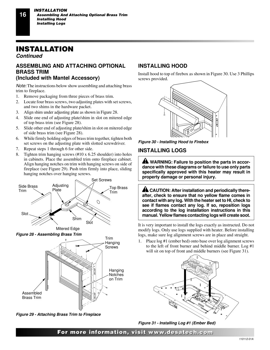
INSTALLING LOGS
![]() WARNING: Failure to position the parts in accor- dance with these diagrams or failure to use only parts specifically approved with this heater may result in property damage or personal injury.
WARNING: Failure to position the parts in accor- dance with these diagrams or failure to use only parts specifically approved with this heater may result in property damage or personal injury.
![]() CAUTION: After installation and periodically there- after, check to ensure that no yellow flame comes in contact with any log. With the heater set to HI, check to see if flames contact any log. If so, reposition logs according to the log installation instructions in this manual. Yellow flames contacting logs will create soot.
CAUTION: After installation and periodically there- after, check to ensure that no yellow flame comes in contact with any log. With the heater set to HI, check to see if flames contact any log. If so, reposition logs according to the log installation instructions in this manual. Yellow flames contacting logs will create soot.
It is very important to install the logs exactly as instructed. Do not modify logs. Only use logs supplied with heater. Before installing logs, make sure log alignment screws are in place and straight.
1.Place log #1 (ember bed) onto base over log alignment screws to the left of front burner and behind middle burner. Log #1 will sit on top of front and middle burners (see Figure 31).
Figure 31 - Installing Log #1 (Ember Bed)
![]()
![]()
![]()
![]()
![]() For
For![]()
![]()
![]()
![]()
![]()
![]()
![]()
![]()
![]()
![]()
![]()
![]()
![]() .
.![]()
![]()
![]()
![]() .com
.com![]()
![]()
![]()
![]()
![]()