8
INSTALLATION
Electrical Hookup
Installation Clearances
Installation Sequence
Removing Fireplace Screen And Floor Assembly
INSTALLATION
Continued
ELECTRICAL HOOKUP
This fireplace normally operates under 120 VAC/60 Hz line volt- age. The electrical cord supplied with your fireplace is five feet in length. You must locate fireplace within reach of a 120 volt grounded electrical outlet. If not, you must install an electrical outlet within reach of the fireplace power cord. The GA3555 outlet accessory may be used for
INSTALLATION CLEARANCES
![]() WARNING: Maintain the minimum clearances. If you can, provide greater clearances from floor, ceil- ing, and adjoining wall.
WARNING: Maintain the minimum clearances. If you can, provide greater clearances from floor, ceil- ing, and adjoining wall.
MINIMUM CLEARANCE TO
COMBUSTIBLE MATERIALS
Top | Left and | Bottom |
| Right Sides | and Rear |
0" | 16" | 0" |
|
|
|
Carefully follow the instructions below. This will ensure safe installation.
Minimum Clearances For Side Combustible Material, Side Wall, and Ceiling
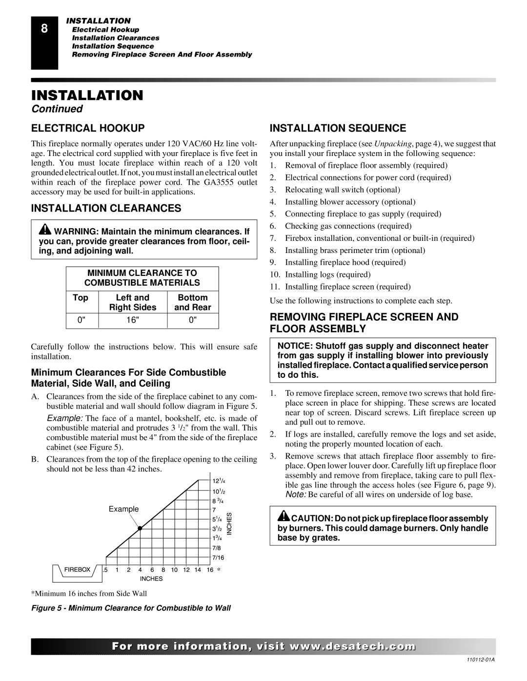
A.Clearances from the side of the fireplace cabinet to any com- bustible material and wall should follow diagram in Figure 5.
Example: The face of a mantel, bookshelf, etc. is made of combustible material and protrudes 3 1/2" from the wall. This combustible material must be 4" from the side of the fireplace cabinet (see Figure 5).
B.Clearances from the top of the fireplace opening to the ceiling should not be less than 42 inches.
Example |
* |
*Minimum 16 inches from Side Wall
Figure 5 - Minimum Clearance for Combustible to Wall
INSTALLATION SEQUENCE
After unpacking fireplace (see Unpacking, page 4), we suggest that you install your fireplace system in the following sequence:
1.Removal of fireplace floor assembly (required)
2.Electrical connections for power cord (required)
3.Relocating wall switch (optional)
4.Installing blower accessory (optional)
5.Connecting fireplace to gas supply (required)
6.Checking gas connections (required)
7.Firebox installation, conventional or
8.Installing brass perimeter trim (optional)
9.Installing fireplace hood (required)
10.Installing logs (required)
11.Installing fireplace screen (required)
Use the following instructions to complete each step.
REMOVING FIREPLACE SCREEN AND FLOOR ASSEMBLY
NOTICE: Shutoff gas supply and disconnect heater from gas supply if installing blower into previously installed fireplace. Contact a qualified service person to do this.
1.To remove fireplace screen, remove two screws that hold fire- place screen in place for shipping. These screws are located near top of screen. Discard screws. Lift fireplace screen up and pull out to remove.
2.If logs are installed, carefully remove the logs and set aside, noting the properly mounted location of each.
3.Remove screws that attach fireplace floor assembly to fire- place. Open lower louver door. Carefully lift up fireplace floor assembly and remove from fireplace, taking care to pull flex- ible gas line through the access holes (see Figure 6, page 9). Note: Be careful of all wires on underside of log base.
![]() CAUTION: Do not pick up fireplace floor assembly by burners. This could damage burners. Only handle base by grates.
CAUTION: Do not pick up fireplace floor assembly by burners. This could damage burners. Only handle base by grates.
![]()
![]()
![]()
![]()
![]() For
For![]()
![]()
![]()
![]()
![]()
![]()
![]()
![]()
![]()
![]()
![]()
![]()
![]() .
.![]()
![]()
![]()
![]() .com
.com![]()
![]()
![]()
![]()
![]()