FASTENING PLANER TO SUPPORTING SURFACE
![]() During operation, if there is any tendency for the planer to tip over, slide or “walk” across the supporting surface, the planer must be secured to the supporting surface. Four holes (two of which are at (A) Fig. 9) are provided for this purpose.
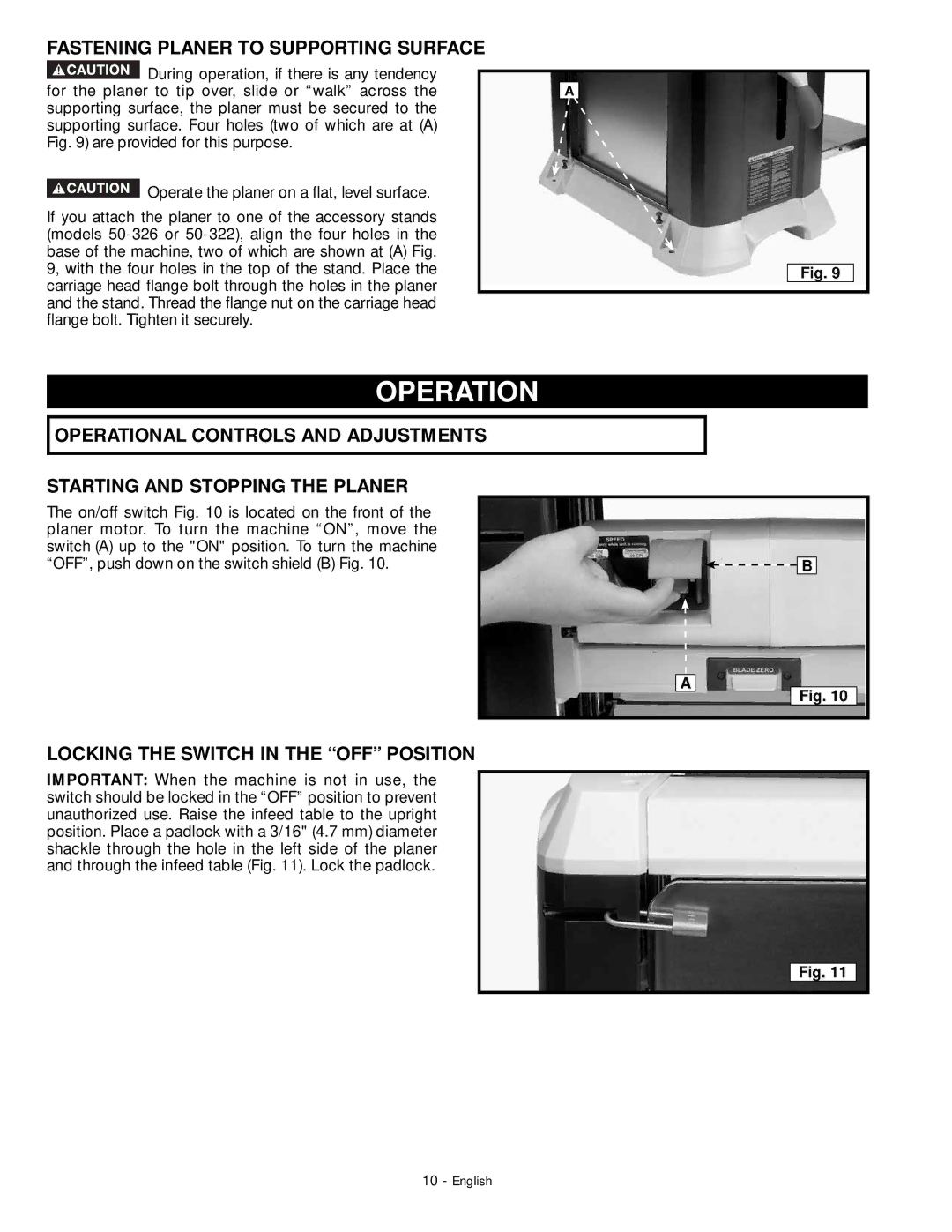
During operation, if there is any tendency for the planer to tip over, slide or “walk” across the supporting surface, the planer must be secured to the supporting surface. Four holes (two of which are at (A) Fig. 9) are provided for this purpose.
![]() Operate the planer on a flat, level surface.
Operate the planer on a flat, level surface.
If you attach the planer to one of the accessory stands (models
A
Fig. 9
OPERATION
OPERATIONAL CONTROLS AND ADJUSTMENTS
STARTING AND STOPPING THE PLANER
The on/off switch Fig. 10 is located on the front of the planer motor. To turn the machine “ON”, move the switch (A) up to the "ON" position. To turn the machine “OFF”, push down on the switch shield (B) Fig. 10.
LOCKING THE SWITCH IN THE “OFF” POSITION
IMPORTANT: When the machine is not in use, the switch should be locked in the “OFF” position to prevent unauthorized use. Raise the infeed table to the upright position. Place a padlock with a 3/16" (4.7 mm) diameter shackle through the hole in the left side of the planer and through the infeed table (Fig. 11). Lock the padlock.
![]()
![]() B
B
A
Fig. 10
Fig. 11
10 - English