LEVELING TABLE EXTENSIONS
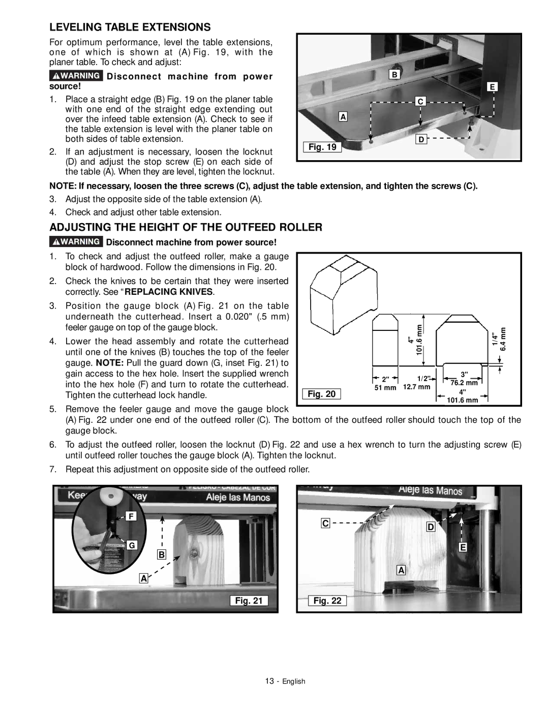
For optimum performance, level the table extensions, one of which is shown at (A) Fig. 19, with the planer table. To check and adjust:
 Disconnect machine from power source!
1.Place a straight edge (B) Fig. 19 on the planer table with one end of the straight edge extending out over the infeed table extension (A). Check to see if the table extension is level with the planer table on both sides of table extension.
2.If an adjustment is necessary, loosen the locknut
(D) and adjust the stop screw (E) on each side of the table (A). When they are level, tighten the locknut.
B |
E |
C |
A |
D |
Fig. 19 |
NOTE: If necessary, loosen the three screws (C), adjust the table extension, and tighten the screws (C).
3.Adjust the opposite side of the table extension (A).
4.Check and adjust other table extension.
ADJUSTING THE HEIGHT OF THE OUTFEED ROLLER
![]() Disconnect machine from power source!
Disconnect machine from power source!
1. | To check and adjust the outfeed roller, make a gauge |
|
|
|
|
| block of hardwood. Follow the dimensions in Fig. 20. |
|
|
|
|
2. | Check the knives to be certain that they were inserted |
|
|
|
|
| correctly. See “REPLACING KNIVES. |
|
|
|
|
3. | Position the gauge block (A) Fig. 21 on the table |
|
|
|
|
| underneath the cutterhead. Insert a 0.020" (.5 mm) |
|
|
|
|
| feeler gauge on top of the gauge block. |
|
| 4" 101.6mm |
|
4. | Lower the head assembly and rotate the cutterhead |
|
|
| |
| until one of the knives (B) touches the top of the feeler |
|
|
| |
| gauge. NOTE: Pull the guard down (G, inset Fig. 21) to |
|
|
|
|
| gain access to the hex hole. Insert the supplied wrench | 2" | 1/2" | 3" | |
| into the hex hole (F) and turn to rotate the cutterhead. | 76.2 mm | |||
|
| 51 mm | 12.7 mm | ||
| Tighten the cutterhead lock handle. | Fig. 20 |
|
| 4" |
|
|
|
|
| 101.6 mm |
5.Remove the feeler gauge and move the gauge block
(A) Fig. 22 under one end of the outfeed roller (C). The bottom of the outfeed roller should touch the
gauge block.
1/4" 6.4 mm
top of the
6.To adjust the outfeed roller, loosen the locknut (D) Fig. 22 and use a hex wrench to turn the adjusting screw (E) until outfeed roller touches the gauge block (A). Tighten the locknut.
7.Repeat this adjustment on opposite side of the outfeed roller.
![]()
![]() F
F
G
B
A
C![]()
A
D
E
Fig. 21
Fig. 22
13 - English