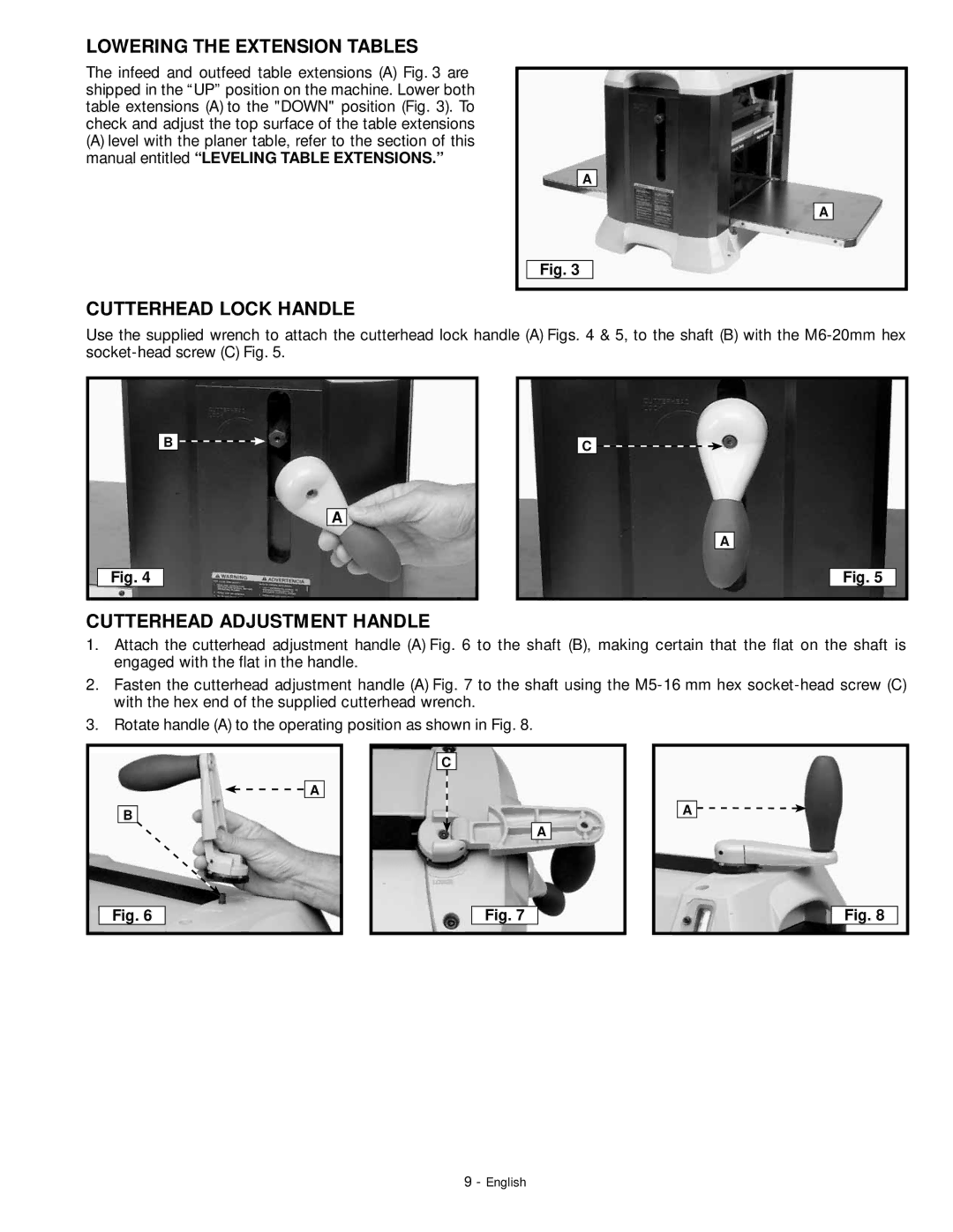
LOWERING THE EXTENSION TABLES
The infeed and outfeed table extensions (A) Fig. 3 are shipped in the “UP” position on the machine. Lower both table extensions (A) to the "DOWN" position (Fig. 3). To check and adjust the top surface of the table extensions
(A)level with the planer table, refer to the section of this manual entitled “LEVELING TABLE EXTENSIONS.”
A
A
Fig. 3
CUTTERHEAD LOCK HANDLE
Use the supplied wrench to attach the cutterhead lock handle (A) Figs. 4 & 5, to the shaft (B) with the
B ![]()
![]()
A
Fig. 4
C![]()
![]()
A
Fig. 5
CUTTERHEAD ADJUSTMENT HANDLE
1.Attach the cutterhead adjustment handle (A) Fig. 6 to the shaft (B), making certain that the flat on the shaft is engaged with the flat in the handle.
2.Fasten the cutterhead adjustment handle (A) Fig. 7 to the shaft using the
3. Rotate handle (A) to the operating position as shown in Fig. 8.
C
![]()
![]() A
A
B
A
A ![]()
![]()
Fig. 6
Fig. 7
Fig. 8
9 - English