ASSEMBLING
GUIDE RAILS
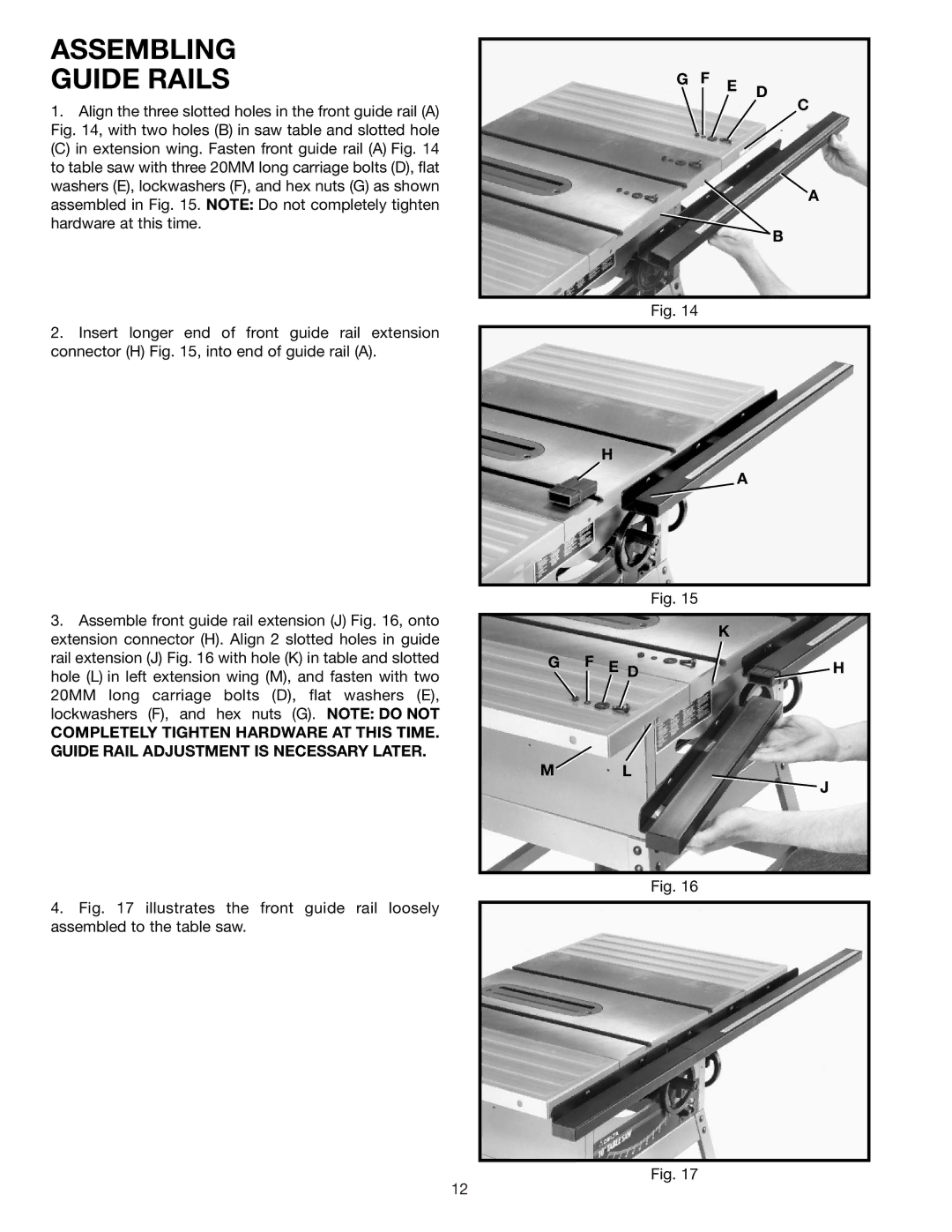
1.Align the three slotted holes in the front guide rail (A) Fig. 14, with two holes (B) in saw table and slotted hole
(C) in extension wing. Fasten front guide rail (A) Fig. 14 to table saw with three 20MM long carriage bolts (D), flat washers (E), lockwashers (F), and hex nuts (G) as shown assembled in Fig. 15. NOTE: Do not completely tighten hardware at this time.
2.Insert longer end of front guide rail extension connector (H) Fig. 15, into end of guide rail (A).
3.Assemble front guide rail extension (J) Fig. 16, onto extension connector (H). Align 2 slotted holes in guide rail extension (J) Fig. 16 with hole (K) in table and slotted hole (L) in left extension wing (M), and fasten with two 20MM long carriage bolts (D), flat washers (E), lockwashers (F), and hex nuts (G). NOTE: DO NOT
COMPLETELY TIGHTEN HARDWARE AT THIS TIME. GUIDE RAIL ADJUSTMENT IS NECESSARY LATER.
4.Fig. 17 illustrates the front guide rail loosely assembled to the table saw.
G F E D
C
A
B
Fig. 14
H
A
Fig. 15
K
G F E D 
 H
H
M L
J
Fig. 16
Fig. 17
12
