MITER GAGE OPERATION AND ADJUSTMENTS
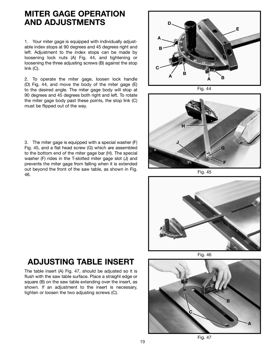
1.Your miter gage is equipped with individually adjust- able index stops at 90 degrees and 45 degrees right and left. Adjustment to the index stops can be made by loosening lock nuts (A) Fig. 44, and tightening or loosening the three adjusting screws (B) against the stop link (C).
2.To operate the miter gage, loosen lock handle
(D) Fig. 44, and move the body of the miter gage (E) to the desired angle. The miter gage body will stop at
90degrees and 45 degrees both right and left. To rotate the miter gage body past these points, the stop link (C) must be flipped out of the way.
3.The miter gage is equipped with a special washer (F) Fig. 45, and a flat head screw (G) which are assembled to the bottom end of the miter gage bar (H). The special washer (F) rides in the T-slotted miter gage slot (J) and prevents the miter gage from falling when it is extended out beyond the front of the saw table, as shown in Fig.
ADJUSTING TABLE INSERT
The table insert (A) Fig. 47, should be adjusted so it is flush with the saw table surface. Place a straight edge or square (B) on the saw table extending over the insert, as shown. If an adjustment to the insert is necessary, tighten or loosen the two adjusting screws (C).
D
E
A
B ![]()
C
B
AA B
Fig. 44
H
J
G
F
Fig. 45
Fig. 46
B
C
![]() A
A
Fig. 47
19