EXTENSION WINGS
 Disconnect the machine from the power source!
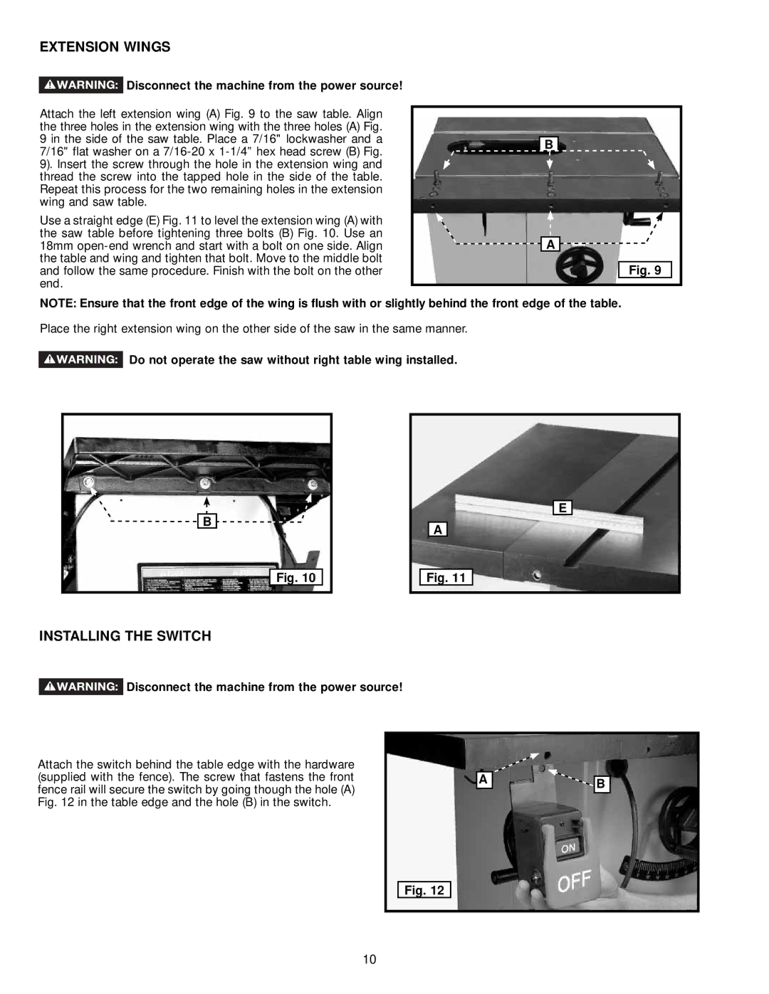
Attach the left extension wing (A) Fig. 9 to the saw table. Align the three holes in the extension wing with the three holes (A) Fig. 9 in the side of the saw table. Place a 7/16" lockwasher and a 7/16" flat washer on a
Use a straight edge (E) Fig. 11 to level the extension wing (A) with the saw table before tightening three bolts (B) Fig. 10. Use an 18mm
B |
A |
Fig. 9 |
NOTE: Ensure that the front edge of the wing is flush with or slightly behind the front edge of the table.
Place the right extension wing on the other side of the saw in the same manner.
![]() Do not operate the saw without right table wing installed.
Do not operate the saw without right table wing installed.
B |
Fig. 10 |
E
A
Fig. 11
INSTALLING THE SWITCH
 Disconnect the machine from the power source!
Attach the switch behind the table edge with the hardware (supplied with the fence). The screw that fastens the front fence rail will secure the switch by going though the hole (A) Fig. 12 in the table edge and the hole (B) in the switch.
A
![]() B
B
Fig. 12
Fig. 12
10