OPERATION
OPERATIONAL CONTROLS AND ADJUSTMENTS
STARTING AND STOPPING THE SAW
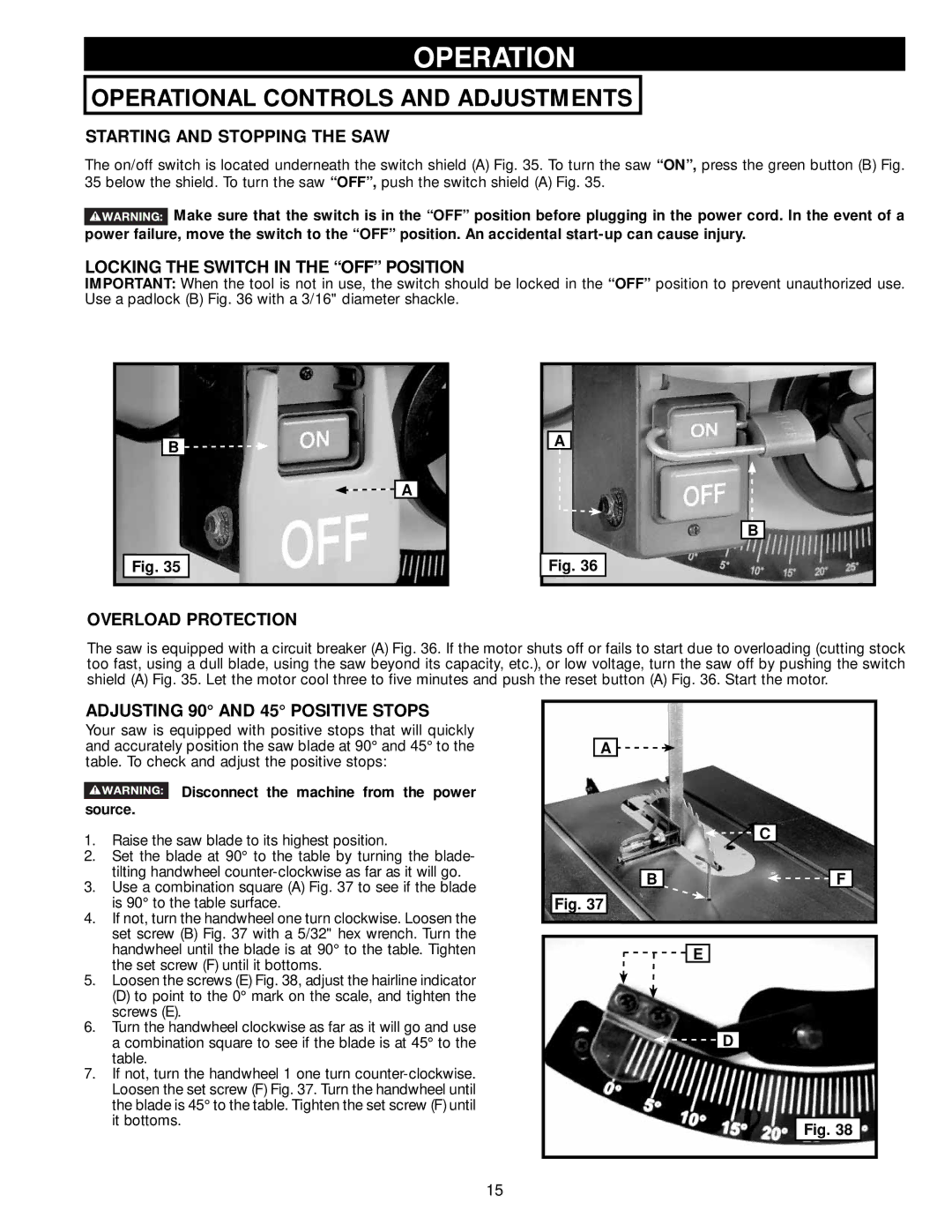
The on/off switch is located underneath the switch shield (A) Fig. 35. To turn the saw “ON”, press the green button (B) Fig. 35 below the shield. To turn the saw “OFF”, push the switch shield (A) Fig. 35.
![]() Make sure that the switch is in the “OFF” position before plugging in the power cord. In the event of a power failure, move the switch to the “OFF” position. An accidental
Make sure that the switch is in the “OFF” position before plugging in the power cord. In the event of a power failure, move the switch to the “OFF” position. An accidental
LOCKING THE SWITCH IN THE “OFF” POSITION
IMPORTANT: When the tool is not in use, the switch should be locked in the Use a padlock (B) Fig. 36 with a 3/16" diameter shackle.
“OFF” position to prevent unauthorized use.
B ![]()
![]()
![]()
![]() A
A
Fig. 35
A
B
Fig. 36
OVERLOAD PROTECTION
The saw is equipped with a circuit breaker (A) Fig. 36. If the motor shuts off or fails to start due to overloading (cutting stock too fast, using a dull blade, using the saw beyond its capacity, etc.), or low voltage, turn the saw off by pushing the switch shield (A) Fig. 35. Let the motor cool three to five minutes and push the reset button (A) Fig. 36. Start the motor.
ADJUSTING 90° AND 45° POSITIVE STOPS
Your saw is equipped with positive stops that will quickly and accurately position the saw blade at 90° and 45° to the table. To check and adjust the positive stops:
 Disconnect the machine from the power source.
1.Raise the saw blade to its highest position.
2.Set the blade at 90° to the table by turning the blade- tilting handwheel
3.Use a combination square (A) Fig. 37 to see if the blade is 90° to the table surface.
4.If not, turn the handwheel one turn clockwise. Loosen the set screw (B) Fig. 37 with a 5/32" hex wrench. Turn the handwheel until the blade is at 90° to the table. Tighten the set screw (F) until it bottoms.
5.Loosen the screws (E) Fig. 38, adjust the hairline indicator
(D) to point to the 0° mark on the scale, and tighten the screws (E).
6.Turn the handwheel clockwise as far as it will go and use a combination square to see if the blade is at 45° to the table.
7.If not, turn the handwheel 1 one turn
A ![]()
![]()
![]()
![]() C
C
B |
| F |
Fig. 37
![]()
![]()
![]() E
E
![]()
![]() D
D
Fig. 38
15