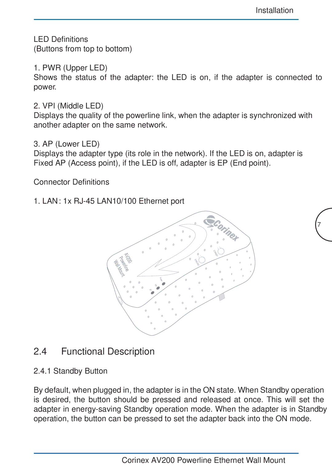
AV200 specifications
DeWalt AV200 is a professional-grade audio-visual technology designed for versatility and high performance, suitable for a variety of construction and job site environments. This innovative tool combines powerful audio capabilities with rugged durability, making it an essential addition to any contractor’s toolkit.One of the standout features of the DeWalt AV200 is its high-output speakers, which deliver clear sound even in noisy environments. The system includes dual 20-watt speakers that provide a robust audio experience, enabling users to enjoy music or listen to important announcements without distortion. Whether on a construction site, in a workshop, or at an outdoor event, the AV200 ensures that audio quality remains uncompromised.
In addition to its impressive sound output, the DeWalt AV200 is equipped with Bluetooth connectivity, allowing users to seamlessly connect their smartphones, tablets, or other Bluetooth-enabled devices. This feature enhances convenience, giving users the freedom to stream music or access hands-free calls without being tethered to a device. With a Bluetooth range of up to 100 feet, users can maintain a connection even at a distance, making it perfect for large job sites.
Durability is another key characteristic of the DeWalt AV200. Designed with a rugged exterior, it can withstand harsh job site conditions, including exposure to dust, moisture, and impacts. Its reinforced corners and solid construction ensure longevity, making it a reliable choice for professionals who demand performance in challenging environments.
The DeWalt AV200 also features a long-lasting battery, providing up to 15 hours of playtime on a single charge. This extended battery life allows users to work throughout the day without worrying about recharging, making it ideal for lengthy projects or outdoor work.
Another notable aspect of the AV200 is its user-friendly interface. It features large, intuitive controls that facilitate easy operation, even when wearing gloves. Additionally, the system includes an auxiliary input for connecting non-Bluetooth devices, ensuring compatibility with a wide range of audio sources.
Overall, the DeWalt AV200 stands out as a versatile audio-visual tool that combines performance, durability, and user-friendly features, making it a vital asset for any professional. Its ability to deliver high-quality sound in demanding environments, along with its robust construction and convenient connectivity options, sets it apart as an exceptional choice for those in the construction and trades industries.

