English
Accessories
Recommended accessories for use with your tool are available at extra cost from your local service center.
![]() CAUTION: The use of any
CAUTION: The use of any
If you need assistance in locating any accessory, please contact DEWALT Industrial Tool Co., 701 East Joppa Road, Baltimore, MD 21286 or call
Bench Mounting
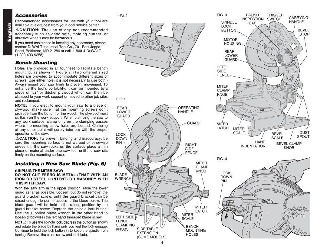
Holes are provided in all four feet to facilitate bench mounting, as shown in Figure 2. (Two different sized holes are provided to accommodate different sizes of screws. Use either hole, it is not necessary to use both.) Always mount your saw firmly to prevent movement. To enhance the tool’s portability, it can be mounted to a piece of 1/2" or thicker plywood which can then be clamped to your work support or moved to other job sites and reclamped.
NOTE: If you elect to mount your saw to a piece of plywood, make sure that the mounting screws don’t protrude from the bottom of the wood. The plywood must sit flush on the work support. When clamping the saw to any work surface, clamp only on the clamping bosses where the mounting screw holes are located. Clamping at any other point will surely interfere with the proper operation of the saw.
![]() CAUTION: To prevent binding and inaccuracy, be sure the mounting surface is not warped or otherwise uneven. If the saw rocks on the surface place a thin piece of material under one saw foot until the saw sits firmly on the mounting surface.
CAUTION: To prevent binding and inaccuracy, be sure the mounting surface is not warped or otherwise uneven. If the saw rocks on the surface place a thin piece of material under one saw foot until the saw sits firmly on the mounting surface.
Installing a New Saw Blade (Fig. 5)
(UNPLUG THE MITER SAW)
DO NOT CUT FERROUS METAL (THAT WITH AN IRON OR STEEL CONTENT) OR MASONRY WITH THIS MITER SAW.
With the saw arm in the upper position, raise the lower guard as far as possible. Loosen (but do not remove) the guard bracket screw, until the guard bracket can be raised enough to permit access to the blade screw. The blade guard will be held in the raised position by the guard bracket screw. Depress the spindle lock button. Use the supplied blade wrench in the other hand to loosen (clockwise) the left hand threaded blade screw.
NOTE: To use the spindle lock, depress the button as shown and rotate the blade by hand until you feel the lock engage. Continue to hold the lock button in to keep the spindle from turning. Remove the blade screw and the blade.
FIG. 1
FIG. 2
REAR
LOWER
GUARD
LOCK
DOWN
PIN
BLADE
WRENCH
LEFT SIDE FENCE CLAMPING
KNOBS SIDE TABLE EXTENSION (SOME MODELS)
OPERATING
HANDLE
GUARD
RIGHT
SIDE
FENCE
MITER
CLAMP
KNOB
MITER
LATCH
MITER
SCALE
BENCH
MOUNTING
HOLES
FIG. 3 | BRUSH | TRIGGER | CARRYING | |
| INSPECTION | SWITCH | ||
SPINDLE | HANDLE | |||
CAP |
| |||
LOCK |
|
| BEVEL | |
BUTTON |
|
| ||
|
|
| STOP | |
MOTOR |
|
|
| |
HOUSING |
|
|
|
REAR
LOWER
GUARD
LEFT
SIDE
FENCE
MITER
CLAMP
KNOB
MITER |
|
|
LATCH MITER |
| DUST |
SCALE | BEVEL |
| SCALE | SPOUT | |
|
| ||
HAND | BEVEL CLAMP | ||
INDENTATION | |||
| KNOB | ||
|
| ||
FIG. 4 |
|
| |
LOCK |
|
| |
DOWN |
|
| |
PIN |
|
| |
55 35
| 50 |
45 | 40 |
| 45 |
4