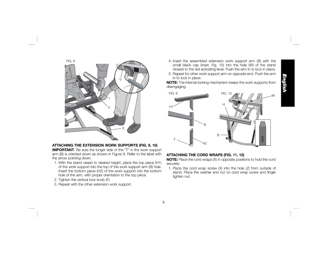
FIG. 8 | 4. | Insert the assembled extension work support arm (B) with the | |
|
| small black cap (inset, Fig. 10) into the hole (W) of the stand | |
|
| closest to the red activating lever. Push the arm in to lock in place. | |
| 5. | Repeat for other work support arm on opposite end. Push the arm | |
V |
| in to lock in place. | |
NOTE: The internal locking mechanism keeps the work supports from | |||
| |||
I | disengaging. | ||
FIG. 9 | FIG. 10 | W |
I |
| |
|
|
V | H |
H1 |
![]() E
E
ATTACHING THE EXTENSION WORK SUPPORTS (FIG. 9, 10)
IMPORTANT: Be sure the longer side of the “T” in the work support arm (B) is oriented down as shown in Figure 9. Refer to the label with the arrow pointing down.
1.With the stand raised to desired height, place the top piece (H1) of the work support into the top of the work support arm (B) hole. Insert the bottom piece (H2) of the work support into the bottom hole of the arm, with proper orientation to the top piece.
2.Tighten the vertical lock knob (F).
3.Repeat with the other extension work support.
B
B ![]()
F
H2
ATTACHING THE CORD WRAPS (FIG. 11, 12)
NOTE: Place the cord wraps (X) in opposite positions to hold the cord securely.
1.Place the cord wrap screw (X) into the hole (Z) from outside of stand. Place the washer and nut on cord wrap screw and finger tighten nut.
English
5