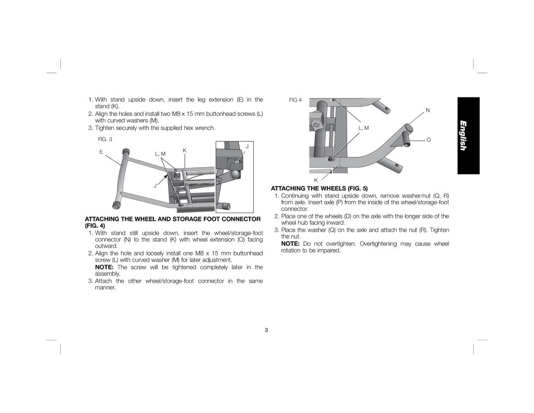
1.With stand upside down, insert the leg extension (E) in the stand (K).
2.Align the holes and install two M8 x 15 mm buttonhead screws (L) with curved washers (M).
3.Tighten securely with the supplied hex wrench.
FIG 4
N
L, M
English
FIG. 3 |
|
|
E | L, M | K |
|
|
J
J |
O
K
ATTACHING THE WHEELS (FIG. 5)
1. | Continuing with stand upside down, remove washer/nut (Q, R) |
| from axle. Insert axle (P) from the inside of the |
| connector. |
2. | Place one of the wheels (D) on the axle with the longer side of the |
ATTACHING THE WHEEL AND STORAGE FOOT CONNECTOR (FIG. 4)
1.With stand still upside down, insert the
2.Align the hole and loosely install one M8 x 15 mm buttonhead screw (L) with curved washer (M) for later adjustment.
NOTE: The screw will be tightened completely later in the assembly.
3.Attach the other
wheel hub facing inward. |
3. Place the washer (Q) on the axle and attach the nut (R). Tighten |
the nut. |
NOTE: Do not overtighten. Overtightening may cause wheel |
rotation to be impaired. |
3