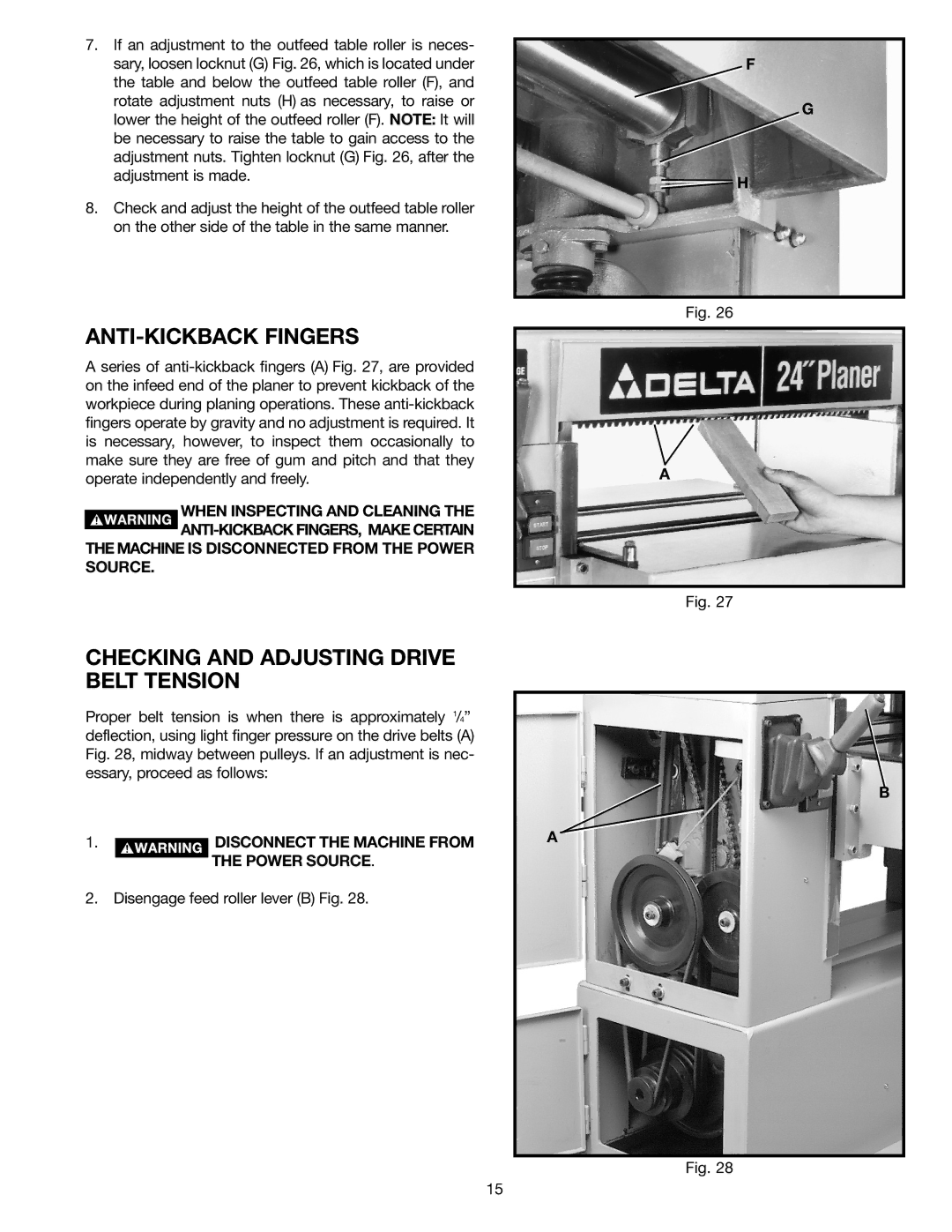
7.If an adjustment to the outfeed table roller is neces- sary, loosen locknut (G) Fig. 26, which is located under the table and below the outfeed table roller (F), and rotate adjustment nuts (H) as necessary, to raise or lower the height of the outfeed roller (F). NOTE: It will be necessary to raise the table to gain access to the adjustment nuts. Tighten locknut (G) Fig. 26, after the adjustment is made.
8.Check and adjust the height of the outfeed table roller on the other side of the table in the same manner.
ANTI-KICKBACK FINGERS
A series of
WHEN INSPECTING AND CLEANING THE
SOURCE.
CHECKING AND ADJUSTING DRIVE BELT TENSION
Proper belt tension is when there is approximately 1/4” deflection, using light finger pressure on the drive belts (A) Fig. 28, midway between pulleys. If an adjustment is nec- essary, proceed as follows:
1. |
|
|
| DISCONNECT THE MACHINE FROM |
|
|
| ||
|
|
| ||
|
|
|
| THE POWER SOURCE. |
|
|
|
|
2. Disengage feed roller lever (B) Fig. 28.
F
G
![]() H
H
Fig. 26
A
Fig. 27
B
A
Fig. 28
15