OPERATION
OPERATIONAL CONTROLS AND ADJUSTMENTS
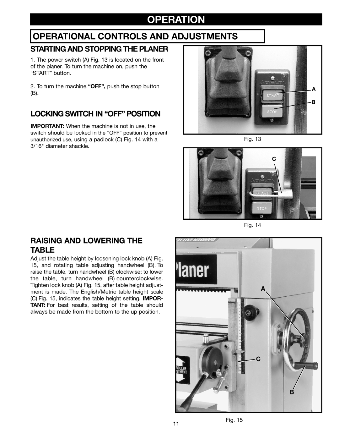
STARTING AND STOPPING THE PLANER
1.The power switch (A) Fig. 13 is located on the front of the planer. To turn the machine on, push the “START” button.
2.To turn the machine “OFF”, push the stop button
(B).
LOCKING SWITCH IN “OFF” POSITION
IMPORTANT: When the machine is not in use, the switch should be locked in the “OFF” position to prevent unauthorized use, using a padlock (C) Fig. 14 with a 3/16" diameter shackle.
A
![]() B
B
Fig. 13
C
Fig. 14
RAISING AND LOWERING THE TABLE
Adjust the table height by loosening lock knob (A) Fig. 15, and rotating table adjusting handwheel (B). To raise the table, turn handwheel (B) clockwise; to lower the table, turn handwheel (B) counterclockwise. Tighten lock knob (A) Fig. 15, after table height adjust- ment is made. The English/Metric table height scale
(C)Fig. 15, indicates the table height setting. IMPOR- TANT: For best results, setting of the table should always be made from the bottom to the up position.
A
![]() C
C
B
11
Fig. 15