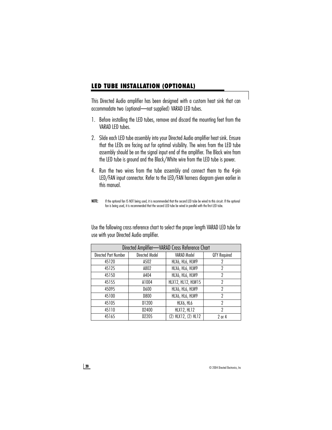
A802, D2205, A1004 specifications
Directed Electronics has established itself as a leader in the automotive electronics industry, offering a wide range of products designed to enhance vehicle security and convenience. Among their notable offerings are the D2205, A802, and A1004, which showcase cutting-edge technologies and features designed to protect vehicles effectively.The Directed Electronics D2205 is a premium remote start system that combines convenience with advanced security features. This system boasts a high range of operation, allowing users to start their vehicles from a significant distance, making it perfect for chilly mornings or hot summer days. One of its standout features is the two-way communication capability, which provides feedback to the user about the vehicle’s status, such as whether the engine is running or if the doors are locked. The D2205 also includes various programmable features that allow users to customize their experience, including the ability to set engine runtime, adjust remote start settings, and even add additional functionalities like keyless entry or trunk release.
The A802 model is designed primarily for alarm and security. It integrates several advanced technologies such as a shock sensor, which detects any unauthorized tampering or movement, triggering audible alerts to deter potential thieves. The A802 also includes a built-in interface for remote start integration, meaning users can combine the security features with remote ignition functionality. Its ease of installation, coupled with support for a wide range of vehicles, makes it a versatile choice for enhancing automotive security. The A802's remote key fob allows users to arm and disarm the system from a distance, adding an extra layer of convenience to vehicle access.
Finally, the Directed Electronics A1004 represents a robust solution in the realm of vehicle security systems. This model features a compact design, making it easy to install without compromising on performance. It is equipped with multiple zone protection, offering a comprehensive security solution that includes perimeter and motion sensors. The A1004 also facilitates passive or active arming options, providing users with flexibility in how they secure their vehicles. Additionally, this system can be integrated with other Directed Electronics products, enabling a more cohesive security approach tailored specifically to user needs.
In summary, Directed Electronics has developed exceptional products like the D2205, A802, and A1004, which reflect their commitment to innovation and quality in vehicle security and convenience. Each model showcases advanced technologies and features aimed at enhancing user experience while ensuring maximum vehicle protection.

