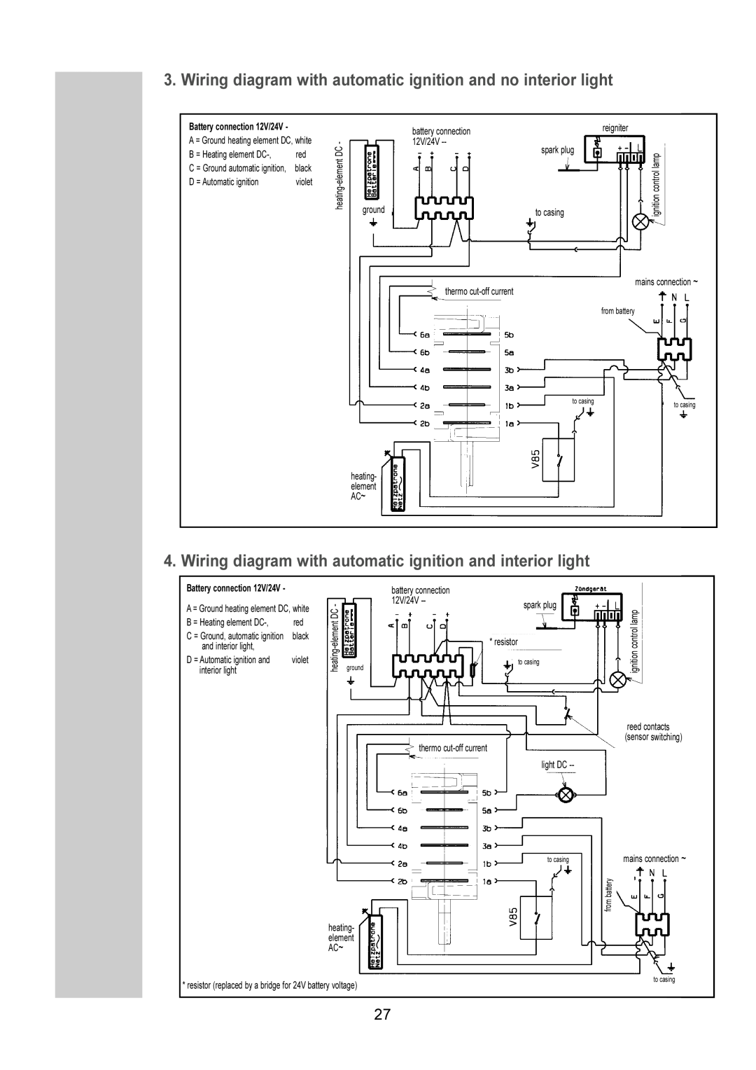
3. Wiring diagram with automatic ignition and no interior light
Battery connection 12V/24V -
A = Ground heating element DC, white
B = Heating element | red |
C = Ground automatic ignition, | black |
D = Automatic ignition | violet |
|
|
|
|
|
|
|
|
|
|
|
|
|
|
|
|
|
| reigniter | |
|
|
| battery connection |
|
|
|
| ||
- |
|
| 12V/24V |
|
|
|
|
|
|
C |
|
|
|
|
| spark plug |
|
| |
Dent |
|
|
|
|
|
|
|
| lamp |
|
|
|
|
|
|
|
| ||
|
|
|
|
|
|
|
| control | |
heati |
|
|
|
|
|
|
|
| ignition |
ground |
|
|
|
|
|
| |||
|
|
| to casing | ||||||
|
|
|
|
|
|
|
|
|
|
|
|
|
|
|
|
|
|
|
|
mains connection ~
thermo
from battery
to casing | to casing |
|
heating- element AC~
4. Wiring diagram with automatic ignition and interior light
Battery connection 12V/24V - |
|
|
|
|
|
|
|
|
|
|
|
|
|
|
|
|
|
|
| battery connection |
|
|
|
|
|
|
|
| |
|
|
|
|
|
| 12V/24V |
|
|
|
|
|
|
|
|
A = Ground heating element DC, white | - |
|
|
|
|
| spark plug |
| ||||||
DC |
|
|
|
|
|
|
|
| ||||||
|
|
|
|
|
|
|
|
|
|
| ||||
B = Heating element | red |
|
|
|
|
|
|
|
|
|
|
| ||
|
|
|
|
|
|
|
|
|
|
| ||||
ground |
|
|
|
|
|
|
|
|
|
| ||||
C = Ground, automatic ignition | black |
|
|
|
|
|
|
|
|
|
| |||
|
|
|
|
|
|
| * resistor |
| ||||||
and interior light, |
|
|
|
|
|
|
|
|
| |||||
|
|
|
|
|
|
|
|
|
|
|
|
|
| |
|
|
|
|
|
|
|
|
|
|
|
|
|
| |
D = Automatic ignition and | violet |
|
|
|
|
|
|
|
|
|
|
|
|
|
|
|
|
|
|
|
|
|
| to casing |
| ||||
interior light |
|
|
|
|
|
|
|
|
|
|
|
|
|
|
|
|
|
|
|
|
|
|
|
|
|
|
|
| |
|
|
|
|
|
|
|
|
|
|
|
|
|
|
|
thermo
light DC
ignition lampcontrol
reed contacts (sensor switching)
|
|
| mains connection ~ | |
to casing | ||||
|
|
|
|
|
|
|
|
|
|
heating- element AC~
|
|
|
* resistor (replaced by a bridge for 24V battery voltage) |
| to casing |
|
| |
|
|
|
27