H. IPI Battery Tray/Battery Installation
The IntelliFire PlusTM system has a battery backup option. Battery longevity and performance will be affected by the service temperatures of this appliance.
NOTICE: Batteries should only be used as a power source in the event of an emergency such as an outage.
The removable battery tray is located in the lower left corner of the appliance next to the lower glass clip. Remove batteries from tray before sliding tray back into appliance. See Figure 2.3.
Anotch on the right side of the tray engages the tray with the appliance. See Figure 2.4. To remove the tray, rotate the left side of the tray outward and pull to the left to disengage the notch. Place the batteries in the tray and return it to the closed position with the notch engaged in the appliance.
Figure 2.3 Battery Tray Located at Bottom Left Side of Appliance
NOTCH
Figure 2.4 Pull Left Side of Tray Out and Disengage Notch
Figure 2.5 Battery Tray Pulled Out
I. Control Module Operation
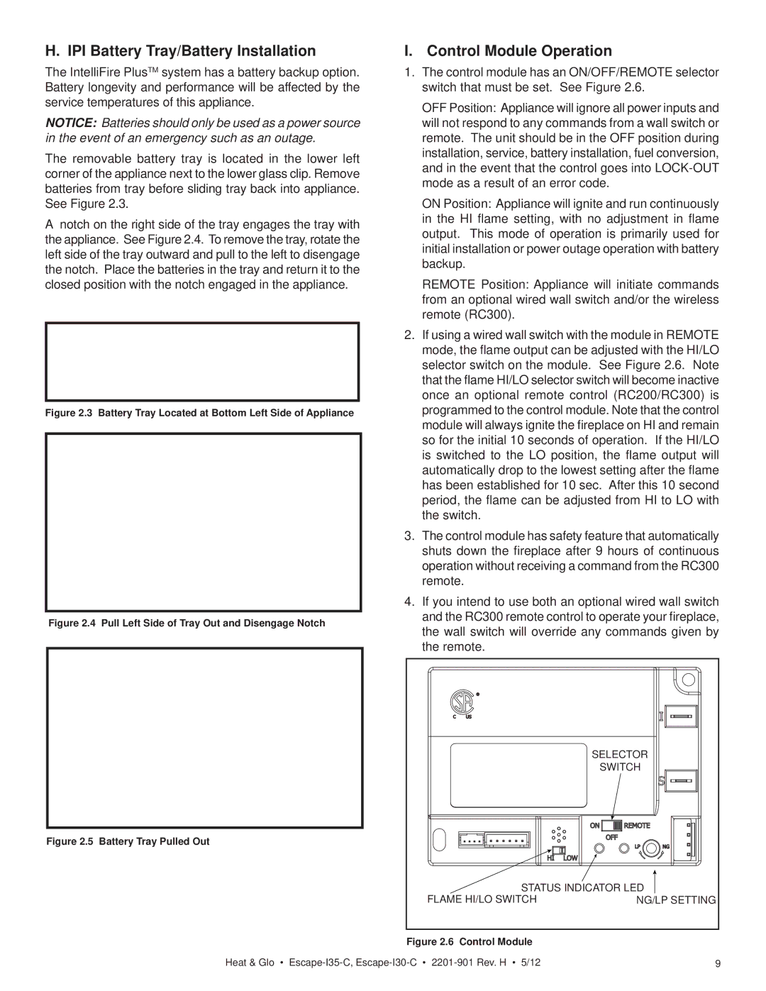
1.The control module has an ON/OFF/REMOTE selector switch that must be set. See Figure 2.6.
OFF Position: Appliance will ignore all power inputs and will not respond to any commands from a wall switch or remote. The unit should be in the OFF position during installation, service, battery installation, fuel conversion, and in the event that the control goes into
ON Position: Appliance will ignite and run continuously in the HI flame setting, with no adjustment in flame output. This mode of operation is primarily used for initial installation or power outage operation with battery backup.
REMOTE Position: Appliance will initiate commands from an optional wired wall switch and/or the wireless remote (RC300).
2.If using a wired wall switch with the module in REMOTE mode, the flame output can be adjusted with the HI/LO selector switch on the module. See Figure 2.6. Note that the flame HI/LO selector switch will become inactive once an optional remote control (RC200/RC300) is programmed to the control module. Note that the control module will always ignite the fireplace on HI and remain so for the initial 10 seconds of operation. If the HI/LO is switched to the LO position, the flame output will automatically drop to the lowest setting after the flame has been established for 10 sec. After this 10 second period, the flame can be adjusted from HI to LO with the switch.
3.The control module has safety feature that automatically shuts down the fireplace after 9 hours of continuous operation without receiving a command from the RC300 remote.
4.If you intend to use both an optional wired wall switch and the RC300 remote control to operate your fireplace, the wall switch will override any commands given by the remote.
| SELECTOR |
| SWITCH |
STATUS INDICATOR LED | |
FLAME HI/LO SWITCH | NG/LP SETTING |
Figure 2.6 Control Module
Heat & Glo • | 9 |