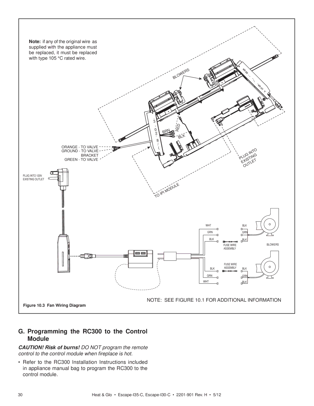
Note: if any of the original wire as supplied with the appliance must be replaced, it must be replaced with type 105 °C rated wire.
BLOWERS
![]()
![]()
![]()
![]()
![]()
![]()
![]()
![]()
![]()
![]() A
A ![]()
![]()
![]()
![]()
![]()
![]()
![]()
![]()
![]()
![]()
![]()
![]()
![]()
![]()
![]()
![]()
![]()
![]() UXI30
UXI30 ![]()
![]()
![]()
![]()
![]()
![]()
![]()
![]()
![]()
![]() LI0
LI0 ![]()
![]()
![]()
![]()
![]()
![]()
![]()
![]() A
A ![]()
![]()
![]() RY
RY ![]()
ORANGE - TO VALVE
GROUND - TO VALVE
BRACKET
GREEN - TO VALVE
PLUG INTO 120V
EXISTING OUTLET
I![]()
![]()
![]()
![]()
![]()
P ![]()
![]()
![]() I
I
M | BRN |
O | |
D |
|
U |
|
L |
|
E |
|
RED
BLK
INTO PLUGEXISTING OUTLET
MODULE IPI TO
WHT
GRN
BLK
FUSE WIRE
ASSEMBLY
FUSE WIRE
BLK ASSEMBLY
GRN
WHT
BLK
GRN
BLK
BLOWERS
BLK
GRN
BLK
Figure 10.3 Fan Wiring Diagram
NOTE: SEE FIGURE 10.1 FOR ADDITIONAL INFORMATION
G. Programming the RC300 to the Control Module
CAUTION! Risk of burns! DO NOT program the remote control to the control module when fireplace is hot.
•Refer to the RC300 Installation Instructions included in appliance manual bag to program the RC300 to the control module.
30 | Heat & Glo • |