E. Installing Adaptor and Termination Cap
CAUTION! Risk of Cuts/Abrasions/Flying Debris. Wear protective gloves and safety glasses during instal- lation. Sheet metal edges are sharp.
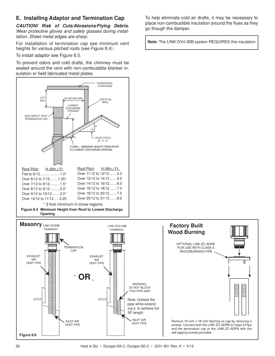
For installation of termination cap see minimum vent heights for various pitched roofs (see Figure 8.4) .
To install adaptor see Figure 8.5.
To prevent odors and cold drafts, the chimney must be sealed around the vent with
HORIZONTAL
OVERHANG
To help eliminate cold air drafts, it may be necessary to place
Note: The
2FT.
MIN.
GAS DIRECT VENT |
TERMINATION CAP |
20 INCHES MIN. | VERTICAL |
LOWEST | WALL |
| |
DISCHARGE |
|
OPENING |
|
X
12
![]() ROOF PITCH
ROOF PITCH
IS X/ 12
H (MIN.) - MINIMUM HEIGHT FROM ROOF TO LOWEST DISCHARGE OPENING
Roof Pitch | H (Min.) Ft. | |
Flat to 6/12 | .................... | 1.0* |
Over 6/12 to 7/12 | 1.25* | |
Over 7/12 to 8/12 | 1.5* | |
Over 8/12 to 9/12 | 2.0* | |
Over 9/12 to 10/12 | 2.5* | |
Over 10/12 to 11/12 | 3.25 | |
Roof Pitch | H (Min.) Ft. | |
Over 11/12 to 12/12 | 4.0 | |
Over 12/12 to 14/12 | 5.0 | |
Over 14/12 to 16/12 | 6.0 | |
Over 16/12 to 18/12 | 7.0 | |
Over 18/12 to 20/12 | 7.5 | |
Over 20/12 to 21/12 | 8.0 | |
* 3 foot minimum in snow regions
Figure 8.4 Minimum Height from Roof to Lowest Discharge
Opening
Masonry | Factory Built | |||||
Installation | Installation | Wood Burning | ||||
|
|
|
|
|
| |
TERMINATION | OPTIONAL | |
FOR USE WITH CLASS A | ||
CAP |
| WOODBURNING PIPE |
EXHAUST | EXHAUST |
|
AIR | AIR |
|
VENT PIPE | VENT PIPE |
|
OR |
| |
| WARNING: |
|
| DO NOT BLOCK |
|
| THIS PIPE END! |
|
| Note: Untwist the |
|
| pipe while extend- |
|
| ing it, to achieve full |
|
| 30’ length. |
|
INLET AIR | INLET AIR | Remove 18 inch x 18 inch flashing on cap by removing 3 |
VENT PIPE | VENT PIPE | screws. Connect both the |
| ||
|
| and the termination cap to the |
Figure 8.6 |
| self tapping screws provided. |
|
| |
26 | Heat & Glo • | |
