6.9.6Wiring diagram
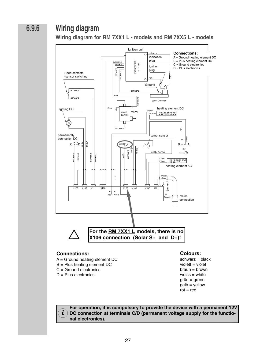
Wiring diagram for RM 7XX1 L - models and RM 7XX5 L - models
ignition unit
Connections:
Reed contacts (sensor switching)
ionisation plug
ignition plug
Ground
gas burner
A = Ground heating element DC B = Plus heating element DC C = Ground electronics
D = Plus electronics
lighting DC
permanently connection DC
C D
heating element DC
valve
temp. sensor
B A
heating element AC
Ground mains connection
For the RM 7XX1 L models, there is no
X106 connection (Solar S+ and D+)!
Connections:Colours:
A = Ground heating element DC B = Plus heating element DC C = Ground electronics
D = Plus electronics
schwarz = black violett = violet braun = brown weiss = white grün = green gelb = yellow rot = red
For operation, it is compulsory to provide the device with a permanent 12V DC connection at terminals C/D (permanent voltage supply for the functio- nal electronics).
27