Data Power Solutions Quick Start Guide
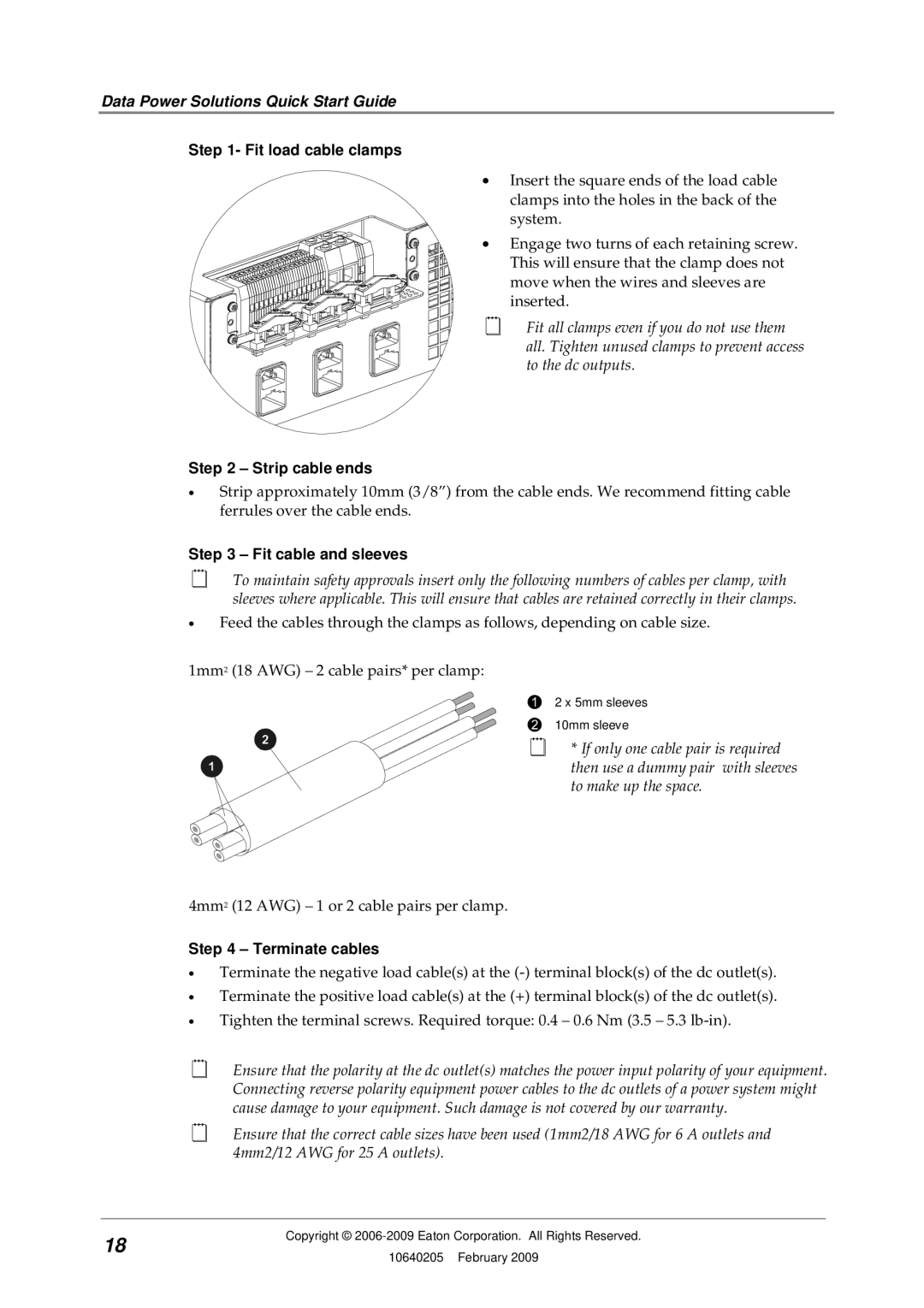
Step 1- Fit load cable clamps
• Insert the square ends of the load cable clamps into the holes in the back of the system.
• Engage two turns of each retaining screw. This will ensure that the clamp does not move when the wires and sleeves are inserted.
Fit all clamps even if you do not use them all. Tighten unused clamps to prevent access to the dc outputs.
Step 2 – Strip cable ends
•Strip approximately 10mm (3/8”) from the cable ends. We recommend fitting cable ferrules over the cable ends.
Step 3 – Fit cable and sleeves
To maintain safety approvals insert only the following numbers of cables per clamp, with sleeves where applicable. This will ensure that cables are retained correctly in their clamps.
•Feed the cables through the clamps as follows, depending on cable size.
1mm2 (18 AWG) – 2 cable pairs* per clamp:
4mm2 (12 AWG) – 1 or 2 cable pairs per clamp.
2 x 5mm sleeves
10mm sleeve
*If only one cable pair is required then use a dummy pair with sleeves to make up the space.
Step 4 – Terminate cables
•Terminate the negative load cable(s) at the
•Terminate the positive load cable(s) at the (+) terminal block(s) of the dc outlet(s).
•Tighten the terminal screws. Required torque: 0.4 – 0.6 Nm (3.5 – 5.3
Ensure that the polarity at the dc outlet(s) matches the power input polarity of your equipment. Connecting reverse polarity equipment power cables to the dc outlets of a power system might cause damage to your equipment. Such damage is not covered by our warranty.
Ensure that the correct cable sizes have been used (1mm2/18 AWG for 6 A outlets and 4mm2/12 AWG for 25 A outlets).
18 | Copyright © | |
10640205 February 2009 | ||
|