Intelligent Technologies (IT.) D77A I/O Module Products
I/O Function
Discrete Input Modules
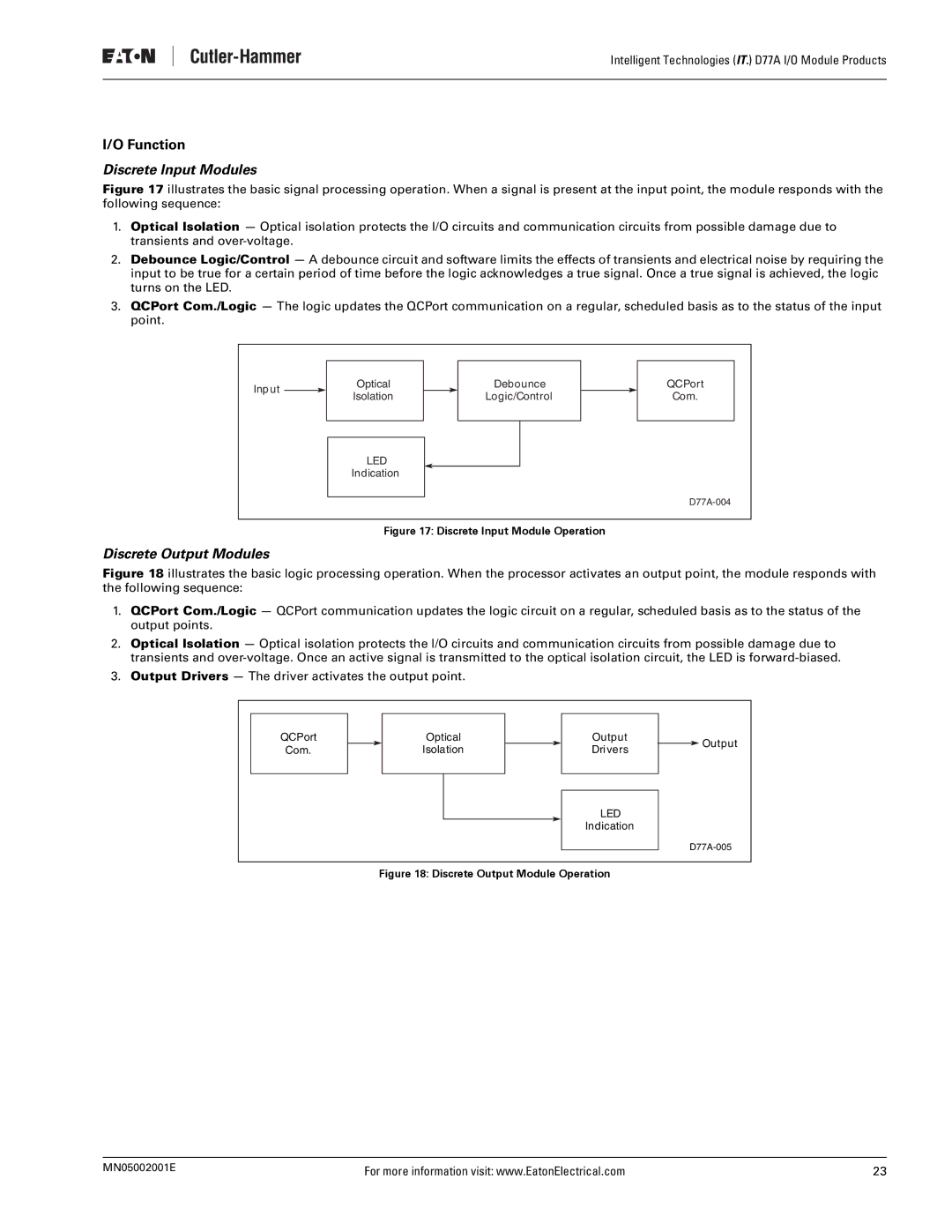
Figure 17 illustrates the basic signal processing operation. When a signal is present at the input point, the module responds with the following sequence:
1.Optical Isolation — Optical isolation protects the I/O circuits and communication circuits from possible damage due to transients and over-voltage.
2.Debounce Logic/Control — A debounce circuit and software limits the effects of transients and electrical noise by requiring the input to be true for a certain period of time before the logic acknowledges a true signal. Once a true signal is achieved, the logic turns on the LED.
3.QCPort Com./Logic — The logic updates the QCPort communication on a regular, scheduled basis as to the status of the input point.
Inp ut | Optical | Debounce | QCPort | |
Isolation | Logic/Control | Com. | ||
| ||||
| LED |
|
| |
| Indication |
|
| |
|
|
|
Figure 17: Discrete Input Module Operation
Discrete Output Modules
Figure 18 illustrates the basic logic processing operation. When the processor activates an output point, the module responds with the following sequence:
1.QCPort Com./Logic — QCPort communication updates the logic circuit on a regular, scheduled basis as to the status of the output points.
2.Optical Isolation — Optical isolation protects the I/O circuits and communication circuits from possible damage due to transients and over-voltage. Once an active signal is transmitted to the optical isolation circuit, the LED is forward-biased.
3.Output Drivers — The driver activates the output point.
QCPort | Optical | Output | Output | |
Com. | Isolation | Dri vers | ||
| ||||
|
| LED |
| |
|
| Indication |
| |
|
|
|
Figure 18: Discrete Output Module Operation
MN05002001E | For more information visit: www.EatonElectrical.com | 23 |