Intelligent Technologies (IT.) D77A I/O Module Products
Analog Inputs
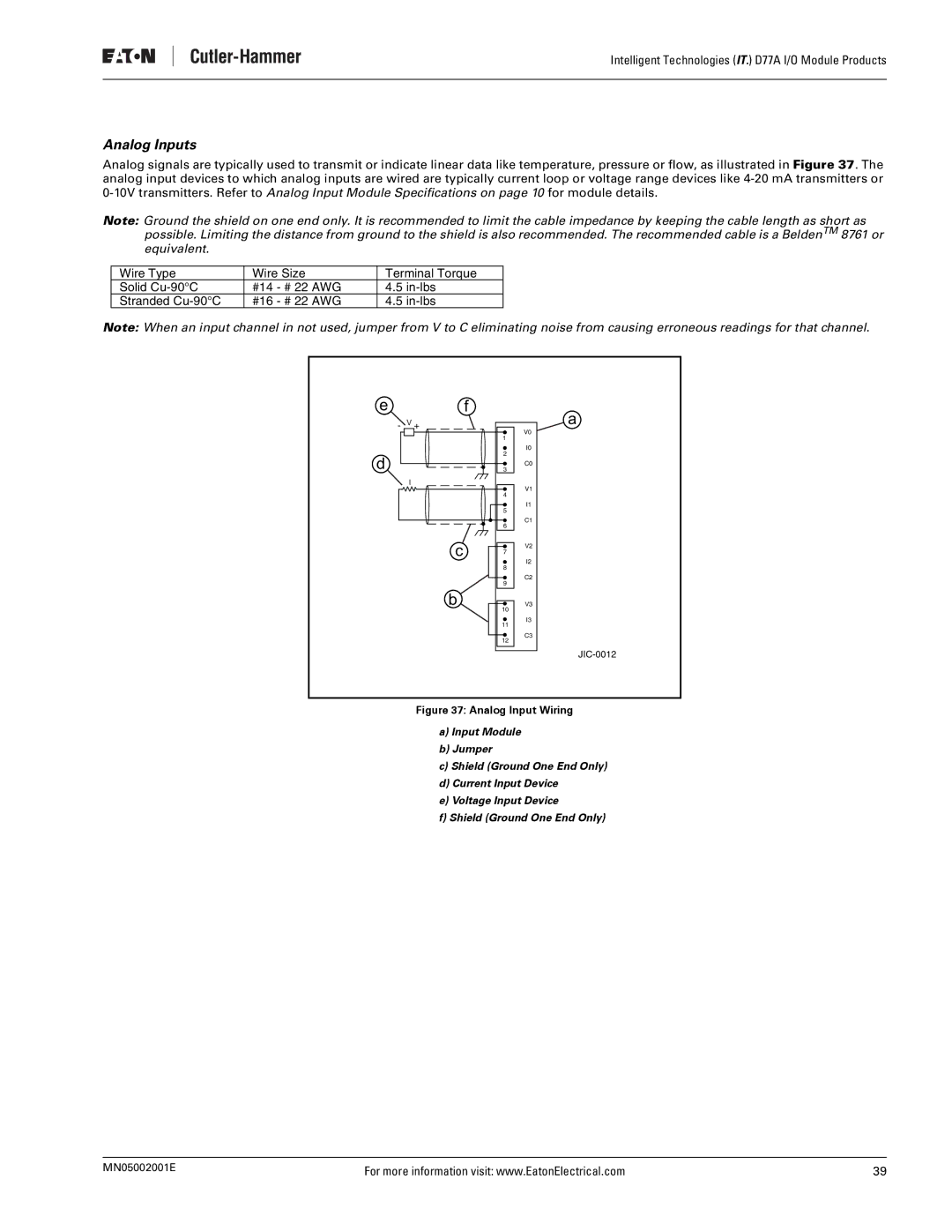
Analog signals are typically used to transmit or indicate linear data like temperature, pressure or flow, as illustrated in Figure 37. The analog input devices to which analog inputs are wired are typically current loop or voltage range devices like
Note: Ground the shield on one end only. It is recommended to limit the cable impedance by keeping the cable length as short as possible. Limiting the distance from ground to the shield is also recommended. The recommended cable is a BeldenTM 8761 or equivalent.
Wire Type | Wire Size | Terminal Torque |
Solid | #14 - # 22 AWG | 4.5 |
Stranded | #16 - # 22 AWG | 4.5 |
Note: When an input channel in not used, jumper from V to C eliminating noise from causing erroneous readings for that channel.
e |
| f |
- | V + | a |
|
| V0 |
|
| 1 |
|
| I0 |
d |
| 2 |
| C0 | |
| 3 | |
| I | V1 |
|
| |
|
| 4 |
|
| I1 |
|
| 5 |
|
| C1 |
|
| 6 |
| c | V2 |
| 7 | |
| I2 | |
|
| |
|
| 8 |
|
| C2 |
|
| 9 |
| b | V3 |
|
| 10 |
|
| I3 |
|
| 11 |
|
| C3 |
|
| 12 |
|
|
Figure 37: Analog Input Wiring
a)Input Module
b)Jumper
c)Shield (Ground One End Only)
d)Current Input Device
e)Voltage Input Device
f)Shield (Ground One End Only)
MN05002001E | For more information visit: www.EatonElectrical.com | 39 |