Model CD5444
For your safety in using CD5444
Page
Page
Page
Page
Table of Contents
How to operate the CD player
How to operate the Sound Adjustment Mode
116
How to operate the receiver with an optional
Operating precautions
About compact discs
About CD accessories
About brand new CDs
About borrowed CDs
How to remove CDs
About irregularly-shaped CDs
About Memory Sticks
Memory Stick
About cleaning the Memory Sticks
Front view
Names of controls and parts
With the front open
Memory Stick security See
About ESN
Key CD security See
ACC security See
Press and hold button 3, then the Func button,
Check that the Power is OFF
Hold both for the more than two seconds
Press the Open button
How to operate the ESN Key CD security
How to program the Key CD
Insert the CD into the slot
How to cancel the Key CD
Insert your Key CD into the slot
How to resume normal operation ESN security lock out
How to change the Key CD
Refer to How to program the Key CD
Press Func button
What happens if an incorrect CD is inserted?
Insert the key CD into the slot
How to record a security code
How to operate the ESN Memory Stick security
Insert the Memory Stick into the slot
Eject the Memory Stick
Press the Func button for more than one second
Refer to Ejecting the Memory Stick on
How to cancel the Memory Stick security
Press the Disc button
Refer to How to cancel the Memory Stick security on
How to change the Memory Stick
Refer to How to record a security code on
How to resume normal operation ESN security lock out
Disc button Func button
Recorded data will read form the Memory Stick
ESN security operating procedure
Once a security code has been recorded, press button
How to operate the ACC security
Func button simultaneously for more than two seconds
How to turn the security indicator on/off
Press and hold button 4, then the Func button,
How to read the Electronic Serial Number
Hold both for more than one second
Turning the power on and off
Basic operation
Press the Open button
Listening to a CD
Insert a CD into the disc slot, label side up
Insert a MG Memory Stick into the Memory Stick slot
Press the Disc button to switch to the Memory Stick
Listening to MG Memory Stick
Mode
Listening to the tuner
Adjusting audio volume
Turn the Audio Control button to the left or right
Bass Mode
Switching audio control modes
VOL Volume Mode
Second to select the item to be adjusted
FAD Fader Mode
Treb Treble Mode
BAL Balance Mode
NON-F NON-FADER Mode
SVC Source Volume Control Mode
Setting examples
Press and hold the Audio Control button until
Settings again
Enabling the loudness control
Loud on display appears on the screen
Press the Disp button for less than one second
Making changes with Display Adjustment Mode
Turn the SEL button in either direction to display setting
Items for selection
Changing illumination Color
Contrast adjustment
Turn the SEL button to adjust contrast
Turn the SEL button to select Contrast Press the SEL button
Function mode is activated
Making changes with Function Mode
Variety of settings can be changed
Press the Func button for less than one second
Press the Func or RTN button to exit function mode
Disabling the guide tone feature for button operation
Clock display on/off
Clock adjustment mode is activated
Setting the Time
This receiver uses the 12-hour display notation
Others
Enabling E-COM feature
Operation assist function
Press the Disc button to switch to the CD player mode
How to operate the CD player
Listening to CDs
Turn the SEL button to the left or right
Fast Forward/Rewind
Playing the beginning of tracks Scan
Press and hold the Seek or Fast button
Press button 5 to repeat the track being played
Repeating the same track Repeat
Playing tracks in random order Random
Press button 6 to play the tracks in random order
Press the button
Ejecting the disc
Press the Open button for less than one second
Remove the disc and press the Open button
Creating a title for a CD
Disc mode
Disc title setting mode is activated
Press the Func button for less than one second while
Press the RTN button
Press the Func or RTN button to exit function mode
CD title is now memorized
Changing a previously set title
CD title being played at this point will be deleted
Deleting a previously created title
Hold button 6 down for more than two seconds
Title has now been deleted
Displaying CD Text
Press the Disp button for more than one second
Playable MP3 file standards
How to operate the MP3 player
What is MP3?
ID3 tags
Media
Format of discs
Playing MP3
File names
Multi-sessions
MP3 playing time display
Listening to MP3 file
Return to the root directory of the CD
Skipping to the next or previous folder
Press button 1 or
Playing the beginning of files Scan
Repeating the same file Repeat
Playing files in random order Random
Displaying title
How to operate the Memory Stick player
Player mode
Fast Forward/Rewind
Repeating the same track Repeat
Ejecting the Memory Stick
Eject the Memory Stick
Music CD
Recording on Memory Stick
Insert the MG Memory Stick to be recording the track
Press the Func button for more than one second
Turn the SEL button to select MS. Press the SEL button
Turn the SEL button to select REC Mode Press the SEL button
Selecting tracks to be recorded
Turn the SEL button to select ALL or 1 Track
Turn the SEL button to select 66kbps, 105kbps or
Setting sound quality
REC quality selection mode is activated
132kbps
Deleting recorded file
Turn the SEL button to select Format Press the SEL button
Format mode is activated, then OK message will appear
Formatting MG Memory Stick quick format
MG memory stick can be formatted
How to operate the tuner
Tuning to a station
Press the SEL button for more than one second until a
Beep is heard
Turn the SEL button to the right or left to tune to
Manually setting stations into memory
Press the FM AM button to switch between FM and AM
Station to be entered in memory
Press the SEL button for less than one second
Preset station scan
To stop the preset scan mode at a desired station, press
SEL button again
Station name settings can be changed
Setting a station name
Tuner mode
Station name setting mode is activated
Press the Func or RTN button to exit function mode
Hold the 6 button down for more than two seconds
Deleting a station name
Station name has now been deleted
DX Mode
Check that the deck is in standby mode
Auto Mode
Press and hold the button 1, then FM AM button,
Changing the radio band location
Press and hold the button 3, then FM AM button,
FM reception differs from AM
FM reception characteristics
Fading out
Reception area of FM broadcasts
Multipath
Position selector
About Sound Adjustment Mode
ISERV sound effect See Customizations
Graphic equalizer
Parametric equalizer
How to operate the Sound Adjustment Mode
Crossover
FcLPF/HPF
Time alignment
Multi-harmonizer
Non-fader phase
ISERV sound effect customizations
Mode will change to sound adjustment mode
Operations during Normal Mode
Turn the SEL button to select a setting item
Press the Sound button for less than one second
DSP Setting
Press the Sound or RTN button to exit sound adjustment mode
Turn the SEL button to select the setting item
Position selector setting Position
Mode will change to position selector setting mode
Turn the SEL button to select Position Press the SEL button
Mode will change to phase selection mode
Non-fader phase selection NON-FADER
Reverse Reverse phase
Normal music mode
Operations during Advance Mode
100
Turn the SEL button to select EQ Press the SEL button
Equalizer adjustment EQ
Switching equalizer modes
Press the SEL button for less than one second
Select the equalizer mode
Fine-tuning EQ functions
Turn the SEL button to select the frequency to be adjusted
When the preset value is changed, the display shows as
Selecting an equalizer mode from memory
Preset pattern stored in memory will be retrieved
~5 Preset ch No
Changed
Making fine adjustments to the parametric equalizer
Mode will change to parametric equalizer adjustment mode
104
105
Turn the SEL button to select a setting item
Simplified time alignment settings T-ALIGN
Mode will change to time alignment setting mode
Turn the SEL button to select T-ALIGN Press the SEL button
Other time alignment items can be set at this time
Position selector setting Position
107
Turn the SEL button to select CAR Type Press the SEL button
Mode will change to car type selection mode
Selecting the type of vehicle CAR Type
108
Installed 109
Tweeter settings Tweeter
Mode will change to tweeter setting mode
Turn the SEL button to select Tweeter Press the SEL button
Turn the SEL button to select Rear SP Press the SEL button
Mode will change to rear speaker position setting mode
Rear speaker position selection Rear SP
110
Crossover adjustment X- Over
Mode will change to multi-harmonizer setting mode
Multi-harmonizer settings Harmonizer
112
113
Data reading mode is activated
Reading sound quality data
115
Data
How to use the Card remote control
Muting the volume
Turning the power on/off
Adjusting the audio volume
Press the PWR button
Press the Mode button
Switching playback modes
How to play the tuner
Selecting the FM/AM band
Switching disc modes
How to play CDs
Selecting preset stations
Selecting a station manually or automatically
Skipping to the next or previous disc
Enabling the optional E-COM feature
Press the Trackaps button. button Skips to the next track
Replacing the battery
Press the Audio Control button, and turn it to
To cut the volume or restore it instantly 122
Left or right
Each press will switch tuner modes from FM1 FM2 FM3 AM 123
Band button Tuneseek buttons
Illuminating the NOB remote control
Press the Track button
Remove the back cover of the remote control unit by
126
How to use an optional NOB remote control
Press the Disc button
Seek button Fast forward Fast button Rewind 128
Playing the beginning of tracks Scan
Random play is not canceled even if a magazine is ejected
Skipping to the next or previous CD
Specifying a CD to play
Turn on the portable audio player and start its play
Switch to AUX mode by pressing the Disc button for
Others
Function
If you have a question
Displayed information for troubleshooting
134
135
Incompatible Files Has Been Inserted
Mode Problem Causes Remedial action Refer To take
136
137
Specifications
Components
Before installation
Installation angle
Qty
Mounting instruction
Mounting the main unit
Install the bezel on the main unit
141
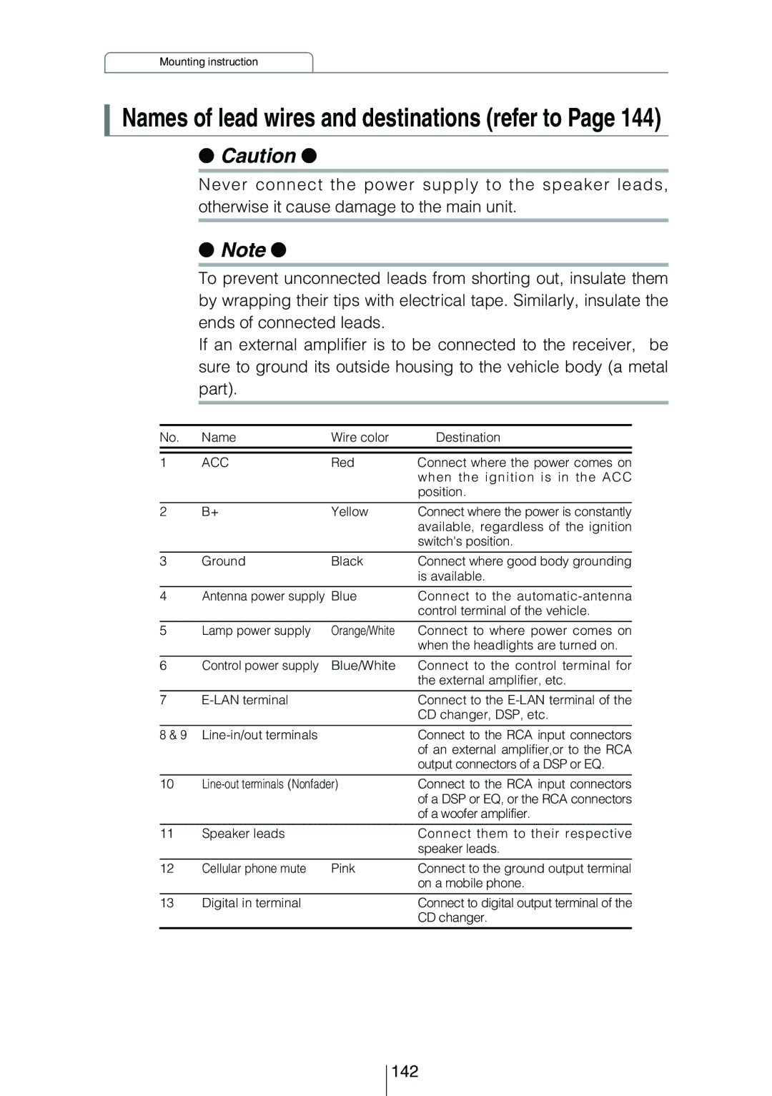
Names of lead wires and destinations refer to
142
System
143
CD5444 Receiver, used alone
144
CD5444 + CH3083 + Power Amplifier
145
CD5444 + CH3083 + CH3083 + Power Amplifier
CD5444 + 2301 + CH3083 + Power Amplifier
147
South Vermont AVENUE, TORRANCE, CA 90502 Phone 310
Phone
Taiwan
150
151
Customer Notice
Serial No