Electrical Adjustments
●Circuit Adjustments
CAUTION: The each circuit has been made by the fine adjustment at factory. Do not attempt to adjust the follow- ing adjustments except requiring the readjustments in servicing otherwise it may cause loss of per- formance and product safety.
[Adjustment Condition] |
|
● Input signal | |
Video signal | |
Computer signal | |
● Picture control mode | “STANDARD” mode unless otherwise noted. |
Note:
*Please refer to “Service Adjustment Menu Operation” for entering to the service mode and adjusting the service data.
Output Voltage adjustment
After replacing the Power Board, PF.C. Board, readjust the Output voltage adjustment as follows.
1.Connect a digital voltmeter to pins 1 (+) and 3
K6D.
2.Adjust the voltage by using VR611 as following.
| AC Input | Reading |
| 230V | 370V ±2V |
or | 120V | 340V ±2V |
Caution:
Be sure to connect the lamp when taking this adjust- ment.
Fan Voltage adjustment
1.Enter the service mode and select group no. “11” and item no. “0”. Set data value to “1”.
2.Connect a digital voltmeter to test point “TP12V1” (+) and chassis ground
3.Connect a digital voltmeter to test point “TP12V2” (+) and chassis ground
4.Select group no. “11” and item no. “0” and set data value to “3”.
5.Connect a digital voltmeter to test point “TP12V1” (+) and chassis ground
6.Connect a digital voltmeter to test point “TP12V2” (+) and chassis ground
Pedestal adjustment
1.Receive the
2.Set to VIDEO mode.
3.Enter the service mode.
[R-PEDESTAL ADJUSTMENT]
4.Connect an oscilloscope to test point “TP201R” (+) and chassis ground
5.Select group no. “3”, item no. “14” and change data value to adjust the pedestal level and black level to be the same level.
6.Connect an oscilloscope to test point “TP201G” (+) and chassis ground
7.Select group no. “3”, item no. “15” and change data value to adjust the pedestal level and black level to be the same level.
8.Connect an oscilloscope to test point “TP201B” (+) and chassis ground
9.Select group no. “3”, item no. “16” and change data value to adjust the pedestal level and black level to be the same level.
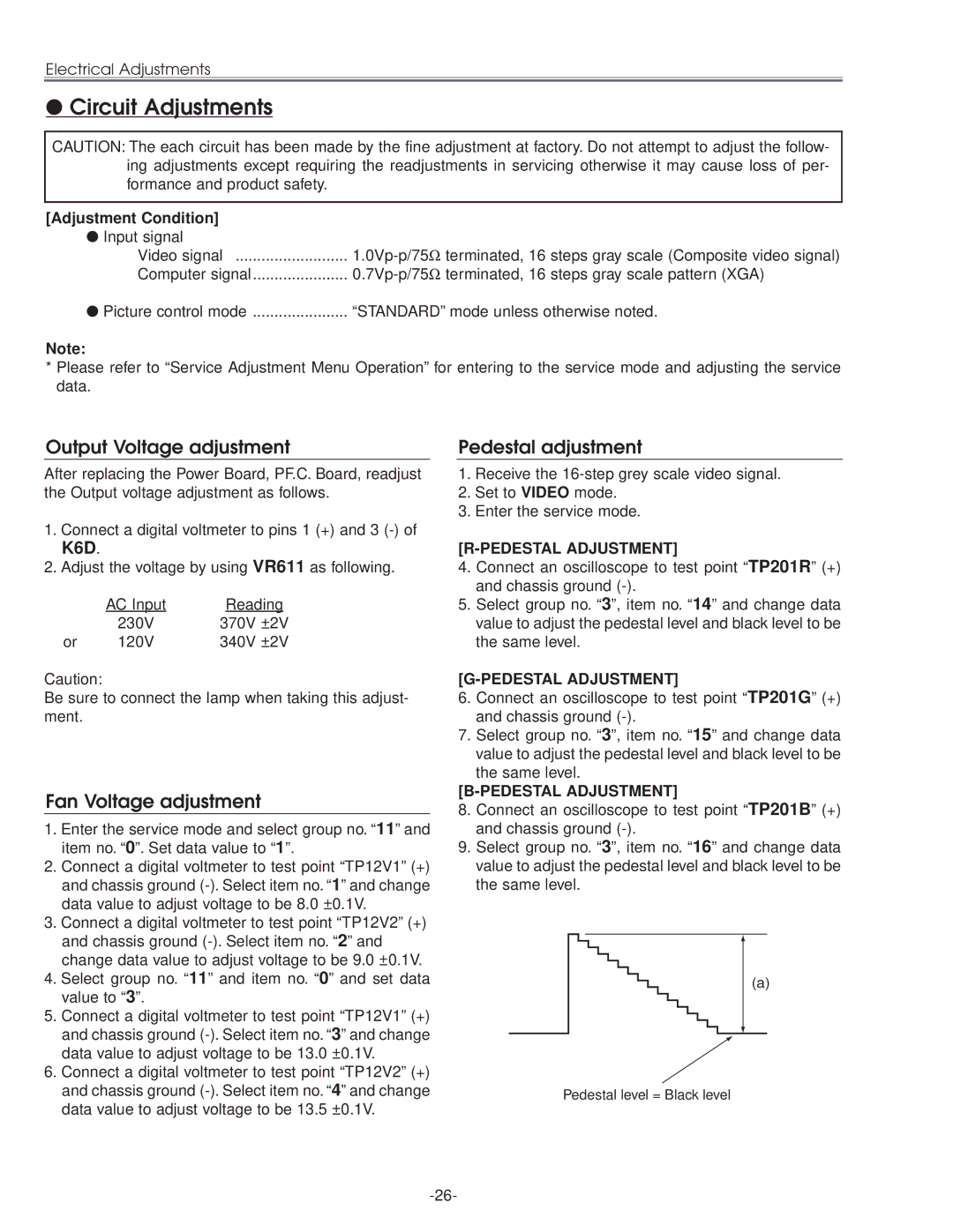
(a)
Pedestal level = Black level