Chassis No. MM8-NB3E00
Model No. LC-NB3E
Contents
Safety Precautions
Safety Instructions
Specifications
Optical Adjustments Electrical Adjustments
Adjustments after Parts Replacement
Fuse
Circuit Protections
Recommendation
Mechanical Disassemblies
Cabinet Top and Control Panel removal
Main Board removal
AV, AV Sub Board and Speaker removal
Front Panel and R/C Board removal
AV board AV Sub board
Lamp Ballast Unit removal
Filter Board removal
Filter board
Power Box Cover and FansFN901, FN906 removal
1Optical Unit removal
AB B
2Optical Unit removal
Power and P.F. Board removal
Interlock Switch lever
Fan FN905 removal
Off from the Cabinet Bottom Fan duct top FN904 FN903 FN902
Integrator Lens-In disassembly
Optical Parts Disassemblies
Projection Lens removal
Condenser Lens-Out disassembly
Condenser lens disassembly
Polarized Glass-In removal
Relay Lens-Out disassembly
Optical Unit Top removal
Polarized Glass-Out removal
Key No. Description
Locations and Directions
LCD Panel/Prism Ass’y removal
LCD Panel/Prism Ass’y Replacement
Important Notice on LCD Panel/Prism Assy Replacement
Mounting Procedure
Order Replacement Lamp
Lamp Replacement
How to reset Lamp Replace Counter
How to check Lamp Replace Counter
Slot B
Optical Adjustments
Contrast adjustment
Before Adjustment
Green b Slot B Moving of slot B Slot D Moving of Slot D
Condenser Lens adjustment
Cyan a Slot B Moving of slot B Moving of slot D
Condenser Lens-Out adjustment
Relay lens-Out adjustment
White a Slot B a Moving of slot B
Slot D Moving of slot D
IC1801 is not defective
Electrical Adjustments
Adjustment Condition
Output Voltage adjustment
Fan Voltage adjustment
Pedestal adjustment
Signal Center Adjustment
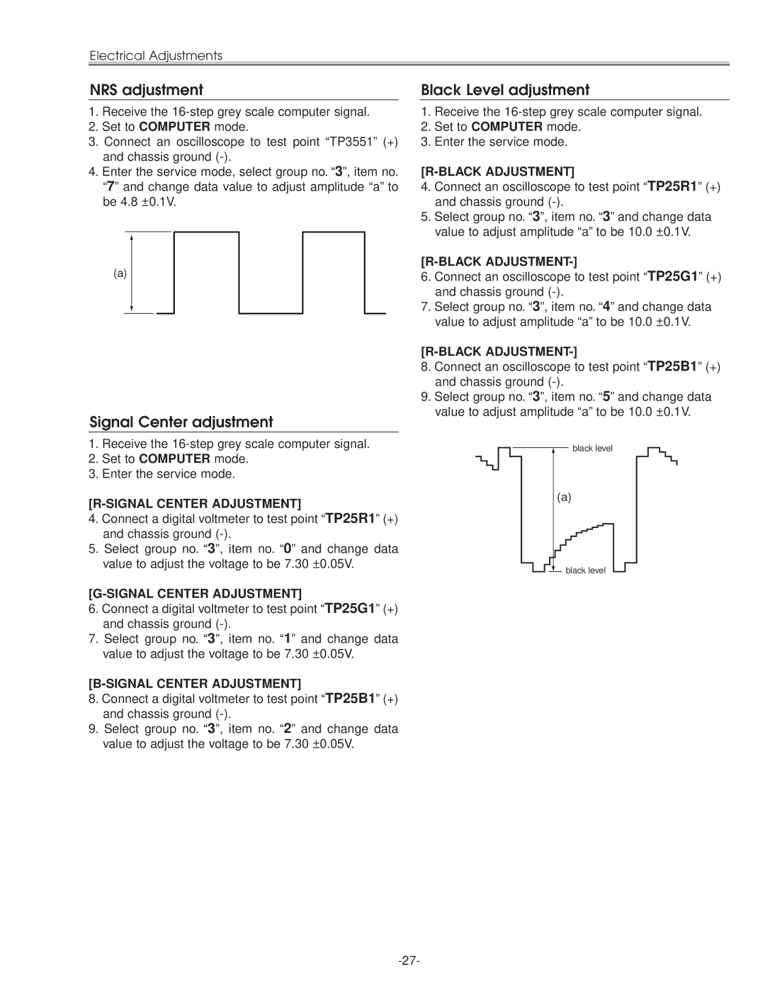
NRS adjustment
Signal Center adjustment
Black Level adjustment
Gain Adjustment
PC Offset adjustment
PC Gain adjustment
Offset Adjustment
Common Center adjustment
AV Gain adjustment
Gamma Shift adjustment
White Balance adjustment
Service Adjustment Data Table
Adjustment Item Initial Value Range Description
Initial Value Range Description
Group 500 ADC
IC301
Troubleshooting
No Power
Abnormality occurs on the power circuit
Power Board Main Board
No picture from all of sources
No Picture
No picture from Video source
No picture from both of Video and Computer sources
AV/PC-RGB-SW
Video Signal processing diagrams
No Sound
Lens Motor Problems
System Control & I/O Port Table IC801
Control Port Functions
MD2
IIC Bus I/O Expander IC1851 Port Functions
IIC Bus I/O Expander IC2181 Port Functions
IIC Bus DA Converter IC1831 Port Functions
IIC Bus DA Converter IC2161 Port Functions
IIC Bus DA Converter IC1581 Port Functions
IIC Bus DA Converter IC2571 Port Functions
Waveforms
VIDEO-IN
Drive TP52R/TP201R Drive TP52G/TP201G Drive TP52B/TP201G
Ballast SW TP28L
Sync OUT IC4101-29 Sync OUT IC4101-28
Sync in TP205
Sync Drive TP62H Sync Drive TP62V DHS Tpdhs DVS Tpdvs
Cleaning with air spray Disassembly Cleaning
Cleaning
IC Block Diagrams
BA7078AF Selector, IC6241 CXA2101AQ RGB Matrix, IC4101
IC Block Diagrams
IC Block Diagrams
ML60851 USB I/F, IC9801 M62393 D/A, IC2571
TB1274AF Video Decoder, IC1101 TA1318N AFC Detector, IC6171
IC Block Diagrams
Page
Read Description in the parts list
Electrical Parts List
OUT of Circuit Board
Assemblied Boards
Board
KEY SW Board
Power Board
610 299 7293 ASSY,PWB,POWER MM8B
1AA0B10C352DA
Fusible RES 22 JH
Line Filter Board
610 294 1708 ASSY,PWB,LINE Filter MS6A
AV Board
IC LT1399CS
FILTER,EMI 100MHZ
AV SUB Board
610 297 1804 ASSY,PWB,AV SUB MD8A
1AA0B10C3700B
Main Board
610 297 1828 ASSY,PWB,MAIN ME8B
1AA0B10C371AA
IC TB1274AF
IC AD8183ARU
C2103
C406
C568
Network 0X4 1/16W
R152
R2549
R3544
R457
FILTER,LP 7MHZ
Accessories
Temp Board
610 297 1873 ASSY,PWB,TEMP ME8A 1AA0B10C3710B
Key No. Part No Description
Mechanical Parts List
Cabinet Parts Optical Parts
Optical Parts List
67 Red Green Blue
Red
52-a
Optical Parts List
MM8-NB3E00
MM8-NB3E00
MM8-NB3E00
Key to better communications Canada