CONNECTING THE PROJECTOR
CONNECTING THE COMPUTER
CONNECTING TO THE COMPUTER INPUT 1 TERMINAL (ANALOG HDB
Personal computers can be connected to the
●Connect the computer to these terminals using the VGA cable and VGA/MAC adapter (provided).
CAUTION: For projectors, the VGA cable provided is designed to reduce RFI (Radio Frequency Interference) emissions. For regulatory compliance reasons, this cable must be used and must not be replaced by any other cable.
CONNECTING TO THE COMPUTER INPUT 1 TERMINAL (DIGITAL MDR
Digital output signal from the computer can be connected to the DIGITAL terminal (MDR
CONNECTING TO THE COMPUTER INPUT 2 JACKS (BNC x 5)
Personal computers can be connected to the computer input (Red, Green, Blue, Horiz. Sync. and Vert. Sync.) on the projector.
●Connect the computer to these jacks using the BNC cables (not provided).
CONNECTING TO THE COMPUTER AUDIO INPUT JACKS (1 and 2)
●Connect audio outputs from your computer to these jacks using the audio cable (not provided).
CONNECTING TO THE
●When the computer is operated by projector's remote control unit, connect three different type of cables (provided) between projector control port and computer mouse port or serial port.
COMPUTER TYPE | CABLE |
IBM Compatible computer with PS/2 mouse port. | Mouse Cable for PS/2 port. |
|
|
IBM Compatible computer with serial port. | Mouse Cable for Serial port. |
|
|
Apple Macintosh computer with ADB mouse port. | Mouse Cable for ADB port. |
|
|
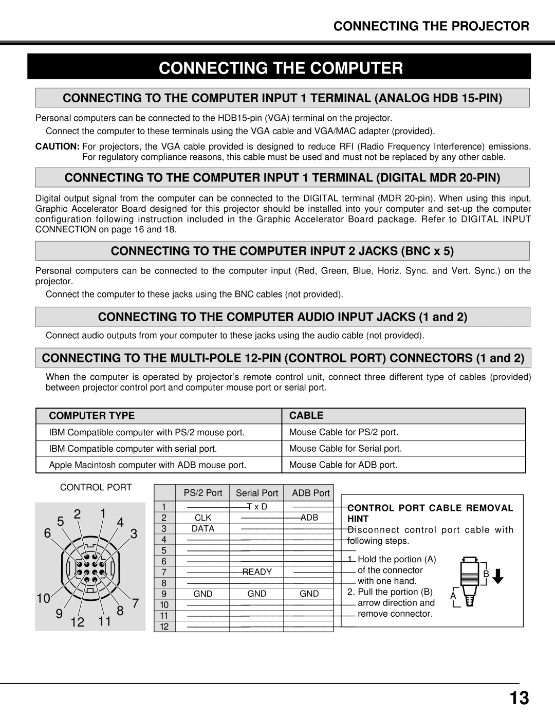
■ CONTROL PORT |
| PS/2 Port | Serial Port | ADB Port | |||
|
|
|
|
| |||
| 2 | 1 |
| 1 | T x D | ||
5 |
| 2 | CLK | ADB | |||
| 4 |
| 3 | DATA | |||
6 |
|
| 3 | ||||
|
| 4 | |||||
|
|
|
| ||||
|
|
|
| 5 | |||
|
|
|
| 6 | |||
|
|
|
| 7 | READY | ||
|
|
|
| 8 | |||
10 |
|
| 7 | 9 | GND | GND | GND |
| 8 | 10 | |||||
9 |
| ||||||
12 |
| 11 | |||||
| 11 |
| 12 | ||||
CONTROL PORT CABLE REMOVAL HINT
Disconnect control port cable with following steps.
1. | Hold the portion (A) |
|
|
|
|
|
|
|
|
|
|
|
|
|
|
|
|
|
|
|
|
|
|
|
|
|
|
|
| ||
| of the connector |
|
|
|
|
|
|
|
|
|
|
|
|
|
|
|
|
|
|
|
|
|
|
|
|
|
|
| B | ||
| with one hand. |
|
|
|
|
|
|
|
|
|
|
|
| ||
|
|
|
|
|
|
|
|
|
|
|
| ||||
|
|
|
|
|
|
|
|
|
|
|
| ||||
|
|
|
|
|
|
|
|
|
|
|
|
|
|
| |
2. | Pull the portion (B) |
|
|
|
|
|
|
|
|
|
|
|
|
|
|
A |
|
|
|
|
|
|
|
| |||||||
|
|
|
|
|
|
|
| ||||||||
arrow direction and remove connector.
13