Multimedia Projector
Network Supported
Memory Viewer
MODEL LC-XB33N
Page
Features and Design
Features and Design Table of Contents To the Owner
Table of Contents
RISK OF ELECTRIC SHOCK DO NOT OPEN
Safety Precaution
To the Owner
Safety Instructions
Moving the Projector
Safety Instructions
Installing the Projector in Proper Position
Air Circulation
Federal Communications Commission Notice
AC Power Cord Requirement
Compliance
Bottom
Part Names and Functions
Front
Back
Part Names and Functions
Rear Terminal
Part Names and Functions
Top Control
Part Names and Functions
Remote Control
To ensure safe operation, please observe the following precautions
Do not bend, drop, or expose the remote control to moisture or heat
Spotlight
Laser Pointer Function
Pointer Function
Part Names and Functions
The code switches sequentially for one pressing the
Part Names and Functions Wireless Mouse Operation
Remote Control Code
more than five seconds to switch between the codes
Open the battery
Remote Control Battery Installation
Remote Control Operating Range
Adjustable Feet
Positioning the Projector
Installation
Notes
Installation
Connecting the AC Power Cord
COMPONENT IN / MONITOR OUT
DVI-VGA Cable DVI Cable USB Cable Audio Cables
Cables used for connection
Connecting to Video Equipment
Installation
Audio cable
Installation Connecting to Component Video Equipment
Enter a PIN code
What is PIN code?
Basic Operation
Turning On the Projector
“Power off?” disappears after 4 seconds
Basic Operation Turning Off the Projector
Top Control
How to Operate the On-Screen Menu
Basic Operation
Remote Control
For detailed functions of each menu, see “Menu Tree” on pages
Basic Operation Menu Bar
For computer source
For video source
Basic Operation
Zoom and Focus Adjustment
Auto Setup Function
Keystone Correction
Volume
Sound Adjustment
Direct Operation
Menu Operation
Normal
Remote Control Operation
Basic Operation
IMAGE button
P-TIMER button
Basic Operation
NO SHOW button
Direct Operation
Computer Input
Input Source Selection RGB Computer 1 Analog/Computer
Notes
Menu Operation
Computer Input
Input Source Selection RGBPC digital, RGBAV HDCP
Direct Operation
Auto
Computer System Selection
Selecting Computer System Manually
Computer Input
Direct Operation
Computer Input Auto PC Adjustment
PC Adjust Menu
Remote Control
Total dots
Computer Input Manual PC Adjustment
Current mode
Fine sync
Computer Input
To clear adjusted data parameters
To store adjusted data
Direct Operation
Image Mode Selection
The selected image mode is check marked
Computer Input
Selected Image mode
Image Adjustment
Image Adjust Menu
Image Adjust Menu icon
Store icon
Screen Size Adjustment
Computer Input
Screen Menu
Computer Input
For zooming in and out the images
Menu Operation
Video Input
Input Source Selection Video, S-video
Direct Operation
Menu Operation
Video Input Input Source Selection Component, RGB Scart 1-pin
Direct Operation
AV System Menu Video or S-Video
Video Input
Video System Selection
Video or S-Video
Menu Operation
Image Mode Selection
Video Input
Direct Operation
Video Input
Image Adjustment
Image Adjust Menu
Gamma
Reset
Video Input
Sharpness
Screen Menu
Screen Size Adjustment
Video Input
Setting
Setting
Blue back
Setting
Use the Point buttons to switch between the options
KeystoneKeystone
Select Yes to stop capturing
Setting
Logo select Capture
Select Yes to capture the projected image
Setting
Change the Logo PIN code lock setting
Enter a Logo PIN code
Change the Logo PIN code
Ceiling Rear
Setting
Time left before Lamp is off
Setting
Power management
Pointer
Setting
Remote control
the Point buttons to switch between the options
Security Key lock and PIN code lock
Setting
Key lock
PIN code lockPIN code lock
Enter a PIN code
Change the PIN code lock setting
Change the PIN code
Setting
Setting
Filter counter
Setting
Factory default
Top Control
Maintenance and Cleaning
WARNING TEMP.. indicator
Top Control
Select Yes again to reset the Filter counter
Maintenance and Cleaning Cleaning the Air Filters
Resetting the Filter Counter
Select Reset and the “Filter counter Reset?” appears
Attaching the Lens Cap
Maintenance and Cleaning
Cleaning the Projection Lens
Cleaning the Projector Cabinet
Model No.. of your projector
Lamp Replacement
ORDER REPLACEMENT LAMP
Replacement Lamp Type No
IF A LAMP EXPLODES, THE FOLLOWING SAFETY PRECAUTIONS SHOULD BE TAKEN
Resetting the Lamp Counter
LAMP HANDLING PRECAUTIONS
Maintenance and Cleaning
Appendix
Troubleshooting
Appendix
Appendix
Appendix
Computer Input
Appendix Menu Tree
Computer Input/Video Input
Sound
AutoSetting
Setting
Video Input
System System Image Select Image Adjust Screen
Projector Condition
Appendix Indicators and Projector Condition
Indicators
Appendix
Compatible Computer Specifications
When selecting these modes, PC adjustment can be limited
Appendix
The specifications are subject to change without notice
Power
Technical Specifications
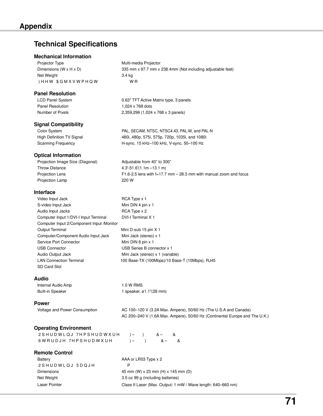
Panel Resolution
Signal Compatibility
Remote Control and Batteries VGA Cable Control cable
Optional Parts
Accessories
Owner’s Manual CD-ROM Quick Reference Guide AC Power Cord
Appendix
PJ Link Notice
This projector is compliant with PJLink Standard Class 1 of JBMIA Japan Business Machine and Information System Industries Association. This projector supports all commands defined by PJLink Class 1 and is verified conformance with PJLink Standard Class
COMPUTER IN 2 /COMPONENT IN /MONITOR OUT ANALOG
Appendix Configurations of Terminals
USB CONNECTOR Series B
SERVICE PORT CONNECTOR Terminal Mini DIN 8-PIN
Factory default set No 1 2 3
PIN Code Number Memo
PIN Code Lock No
Logo PIN Code Lock No
2289.053.52.11
Appendix Dimensions
88.73.49246.39.70
10MAX
China
2007 Eiki International, Inc
U..S..A
Deutschland & Österreich