CAN-BUS
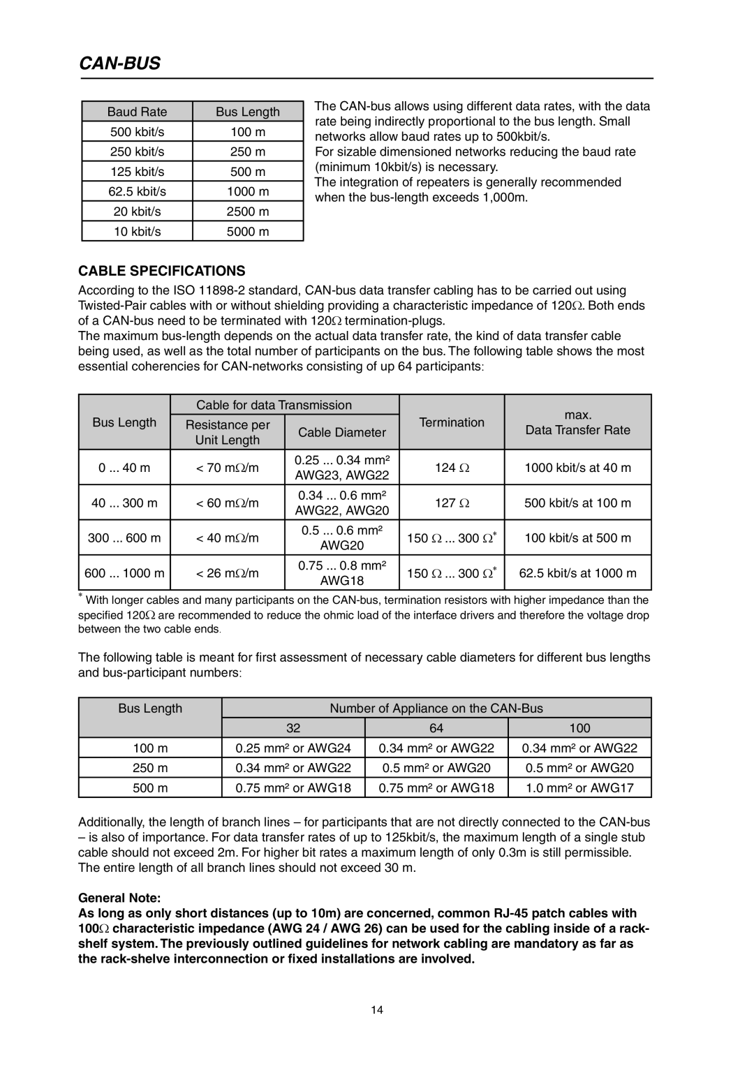
Baud Rate | Bus Length |
500 kbit/s | 100 m |
250 kbit/s | 250 m |
125 kbit/s | 500 m |
62.5 kbit/s | 1000 m |
20 kbit/s | 2500 m |
10 kbit/s | 5000 m |
The
For sizable dimensioned networks reducing the baud rate (minimum 10kbit/s) is necessary.
The integration of repeaters is generally recommended when the
CABLE SPECIFICATIONS
According to the ISO
The maximum
| Cable for data Transmission |
| max. | ||
Bus Length |
|
| Termination | ||
Resistance per |
| ||||
Cable Diameter | Data Transfer Rate | ||||
| Unit Length |
| |||
|
|
|
| ||
|
|
|
|
| |
0 ... 40 m | < 70 mΩ/m | 0.25 ... 0.34 mm² | 124 Ω | 1000 kbit/s at 40 m | |
AWG23, AWG22 | |||||
|
|
|
| ||
|
|
|
|
| |
40 ... 300 m | < 60 mΩ/m | 0.34 ... 0.6 mm² | 127 Ω | 500 kbit/s at 100 m | |
AWG22, AWG20 | |||||
|
|
|
| ||
|
|
|
|
| |
300 ... 600 m | < 40 mΩ/m | 0.5 ... 0.6 mm² | 150 Ω ... 300 Ω* | 100 kbit/s at 500 m | |
AWG20 | |||||
|
|
|
| ||
|
|
|
|
| |
600 ... 1000 m | < 26 mΩ/m | 0.75 ... 0.8 mm² | 150 Ω ... 300 Ω* | 62.5 kbit/s at 1000 m | |
AWG18 | |||||
|
|
|
| ||
*With longer cables and many participants on the
The following table is meant for first assessment of necessary cable diameters for different bus lengths and
Bus Length | Number of Appliance on the | ||
| 32 | 64 | 100 |
100 m | 0.25 mm² or AWG24 | 0.34 mm² or AWG22 | 0.34 mm² or AWG22 |
250 m | 0.34 mm² or AWG22 | 0.5 mm² or AWG20 | 0.5 mm² or AWG20 |
500 m | 0.75 mm² or AWG18 | 0.75 mm² or AWG18 | 1.0 mm² or AWG17 |
Additionally, the length of branch lines – for participants that are not directly connected to the
–is also of importance. For data transfer rates of up to 125kbit/s, the maximum length of a single stub cable should not exceed 2m. For higher bit rates a maximum length of only 0.3m is still permissible. The entire length of all branch lines should not exceed 30 m.
General Note:
As long as only short distances (up to 10m) are concerned, common
14