14Installation Instructions
Gas connection
1.Remove the shipping cap from gas pipe at the rear of the dryer.
IMPORTANT
DO NOT connect the dryer to L.P. gas service without converting the gas valve. An L.P. conversion kit must be installed by a qualified gas technician.
2.Connect a 1/2 inch (1.27 cm) I.D.
Manual | Flare | GAS FLOW | |
Shutoff | Flare | ||
Union | Union | ||
Valve | |||
|
|
Closed![]()
![]()
Nipple | Flexible | Inlet Pipe on |
Open | Connector | Back of Dryer |
All connections must be
IMPORTANT
The supply line must be equipped with an approved manual shutoff valve. This valve should be located in the same room as the dryer and should be in a location that allows ease of opening and closing. Do not block access to the gas shutoff valve.
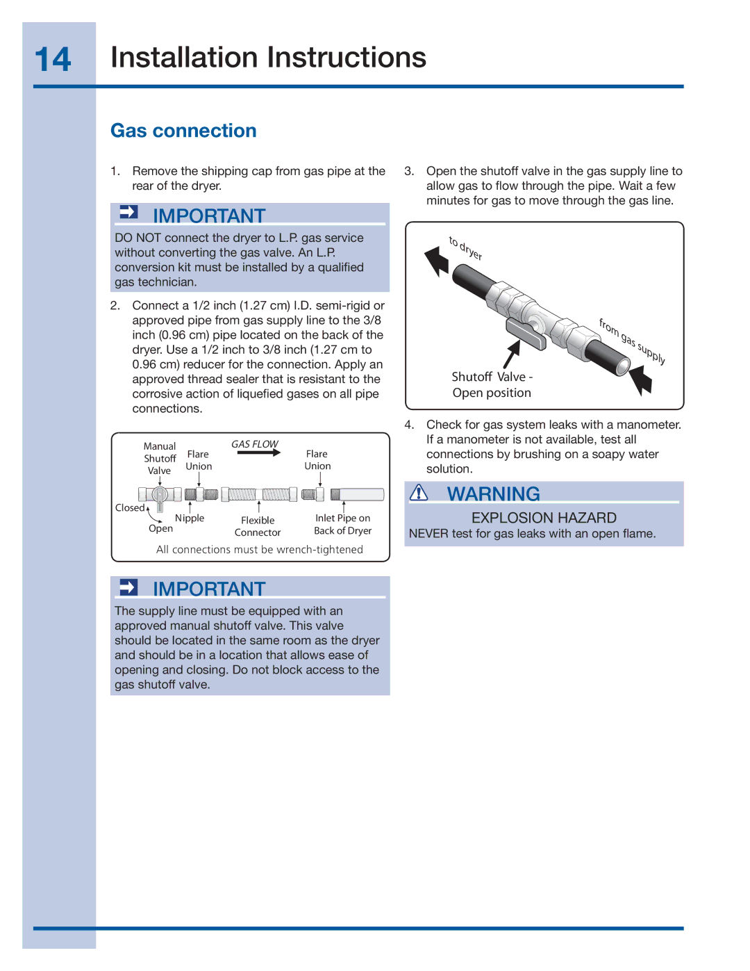
3.Open the shutoff valve in the gas supply line to allow gas to flow through the pipe. Wait a few minutes for gas to move through the gas line.
 to dryer
from | gas | supply |
| ||
|
|
Shutoff Valve -
Open position
4.Check for gas system leaks with a manometer. If a manometer is not available, test all connections by brushing on a soapy water solution.
WARNING
EXPLOSION HAZARD
NEVER test for gas leaks with an open flame.