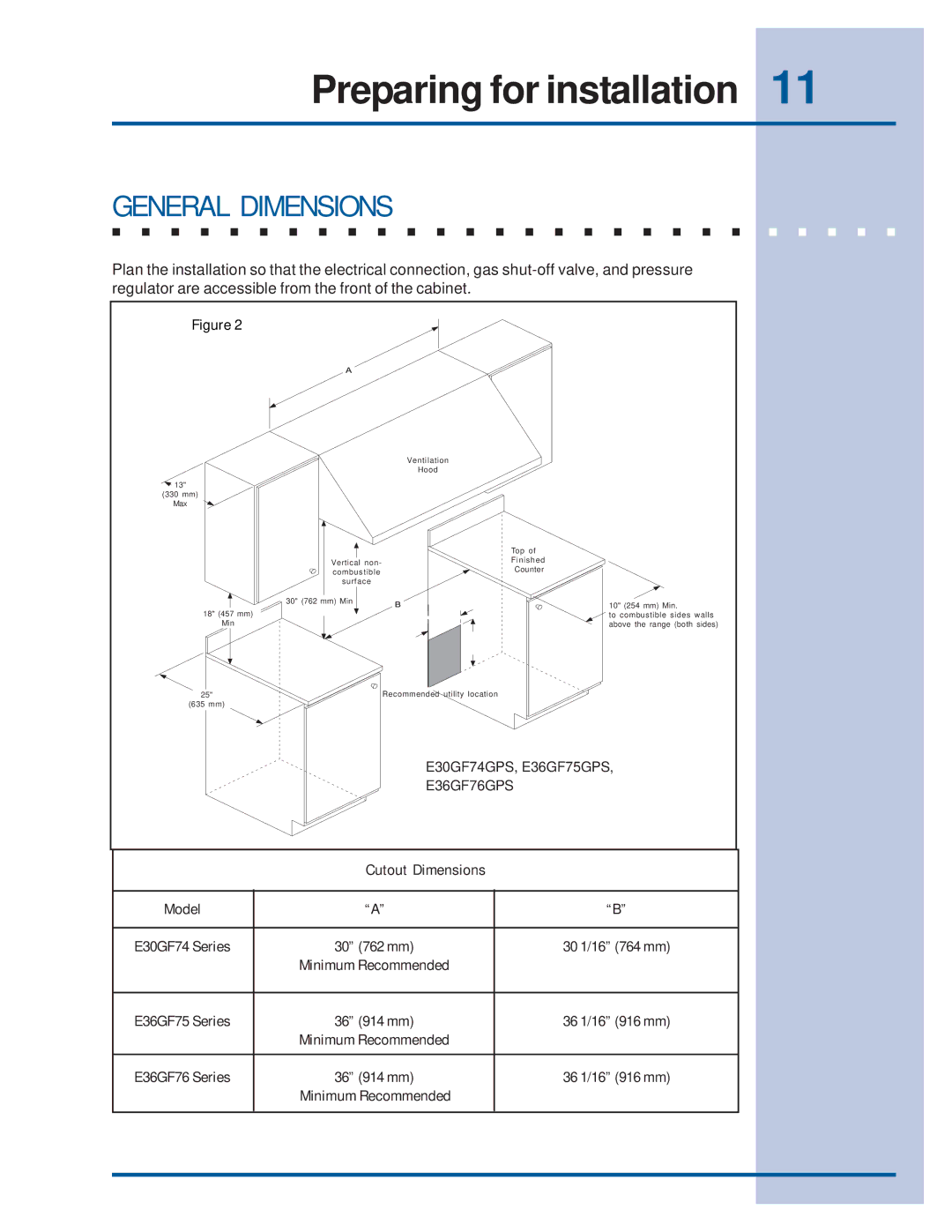
318201761E30GF74GPS, E36GF75GPS, E36GF76GPS specifications
Electrolux has made a significant mark in the home appliance sector, particularly with its advanced range of refrigerators designed for convenience, efficiency, and modern living. Among its notable models, the Electrolux 318201761E30GF74GPS, E36GF76GPS, and E36GF75GPS stand out due to their cutting-edge features and innovative technologies.The Electrolux 318201761E30GF74GPS is designed with a focus on maximizing freshness and minimizing wastage. It includes advanced cooling technologies such as Dual Cooling, which uses independent cooling systems for the refrigerator and freezer compartments. This setup not only preserves food more effectively but also prevents the mingling of odors, ensuring that your food stays fresher for longer.
On the other hand, the E36GF76GPS and E36GF75GPS models boast a spacious interior, optimally designed for organizing groceries. Their custom features include adjustable shelving and ample door storage, allowing users to tailor the space according to their needs. The interior lighting is LED-based, providing bright illumination while utilizing less energy, which aligns with Electrolux's commitment to sustainability.
Another standout feature across these models is the Smart Refrigeration technology that integrates with mobile applications. This feature allows users to monitor and adjust temperature settings remotely, receive alerts regarding door status, and even track food inventories. This level of connectivity integrates seamlessly with today’s smart home setups, providing convenience at your fingertips.
Energy efficiency is a hallmark of Electrolux appliances. These models feature high energy efficiency ratings, which not only help in reducing electricity bills but also contribute to a lower environmental impact. The use of high-quality insulation materials ensures that the cooling system operates effectively while consuming minimal energy.
In terms of design, the sleek stainless steel finish adds a touch of elegance to any kitchen decor. The fingerprint-resistant coating ensures that the exterior remains clean and smudge-free, minimizing maintenance hassle.
In conclusion, the Electrolux 318201761E30GF74GPS, E36GF76GPS, and E36GF75GPS refrigerators are remarkable examples of modern appliance technology. With sophisticated cooling systems, user-friendly smart features, energy efficiency, and timeless design, these models exemplify Electrolux’s commitment to enhancing everyday living through innovation and quality.

