Installation15
INSTALLING THE SUPPORT SYSTEM
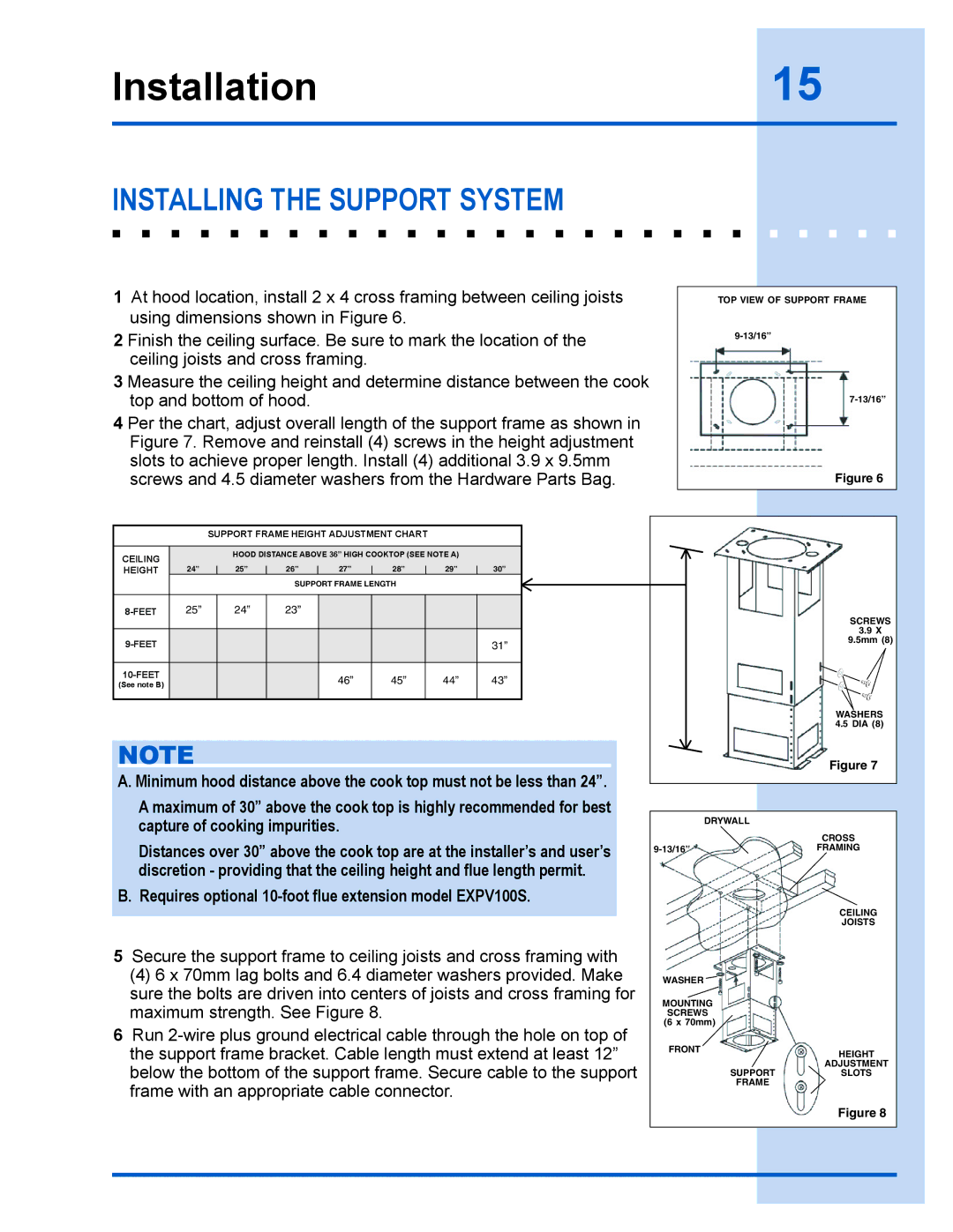
1At hood location, install 2 x 4 cross framing between ceiling joists using dimensions shown in Figure 6.
2 Finish the ceiling surface. Be sure to mark the location of the ceiling joists and cross framing.
3 Measure the ceiling height and determine distance between the cook top and bottom of hood.
4 Per the chart, adjust overall length of the support frame as shown in Figure 7. Remove and reinstall (4) screws in the height adjustment slots to achieve proper length. Install (4) additional 3.9 x 9.5mm screws and 4.5 diameter washers from the Hardware Parts Bag.
TOP VIEW OF SUPPORT FRAME
Figure 6
SUPPORT FRAME HEIGHT ADJUSTMENT CHART
CEILING |
| HOOD DISTANCE ABOVE 36” HIGH COOKTOP (SEE NOTE A) |
| ||||
|
|
|
|
|
|
| |
HEIGHT | 24” | 25” | 26” | 27” | 28” | 29” | 30” |
|
|
| SUPPORT FRAME LENGTH |
|
| ||
|
|
|
|
|
|
|
|
25” | 24” | 23” |
|
|
|
| |
|
|
|
|
|
|
|
|
|
|
|
|
|
| 31” | |
|
|
|
|
|
|
|
|
|
|
| 46” | 45” | 44” | 43” | |
(See note B) |
|
|
| ||||
|
|
|
|
|
|
| |
|
|
|
|
|
|
|
|
NOTE
A. Minimum hood distance above the cook top must not be less than 24”.
A maximum of 30” above the cook top is highly recommended for best capture of cooking impurities.
Distances over 30” above the cook top are at the installer’s and user’s discretion - providing that the ceiling height and flue length permit.
B. Requires optional 10-foot flue extension model EXPV100S.
5Secure the support frame to ceiling joists and cross framing with
(4)6 x 70mm lag bolts and 6.4 diameter washers provided. Make sure the bolts are driven into centers of joists and cross framing for maximum strength. See Figure 8.
6Run
SCREWS
3.9 X
9.5mm (8)
WASHERS 4.5 DIA (8)
Figure 7
DRYWALL
CROSS
CEILING
JOISTS
WASHER ![]()
MOUNTING
SCREWS (6 x 70mm)
FRONT | HEIGHT |
| |
| ADJUSTMENT |
SUPPORT | SLOTS |
FRAME |
|
Figure 8