ADVANCED INSTALLER MENU
Advanced Installer Menu
HUM
OFF – No humidifier equipment
SYS – Humidifier, powered using 24V from system
IND – Humidifier, powered using independent 24V source
DHM
OFF – No dehumidifier equipment
SYS – Dehumidifier, powered using 24V from system
IND – Dehumidifier, powered using independent 24V source
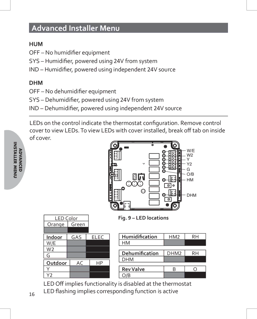
LEDs on the control indicate the thermostat configuration. Remove control cover to view LEDs. To view LEDs with cover installed, break off tab on inside of cover.
![]() W/E
W/E
W2
Y
Y2
G
O/B
HM
DHM
LED Color |
| |
Orange | Green |
|
Indoor | GAS | ELEC |
W/E |
|
|
W2 |
|
|
G |
|
|
Outdoor | AC | HP |
Y |
|
|
Y2 |
|
|
Fig. 9 – LED locations |
| ||
|
|
|
|
| Humidification | HM2 | RH |
| HM |
|
|
|
|
|
|
| Dehumification | DHM2 | RH |
| DHM |
|
|
|
|
|
|
| Rev Valve | B | O |
| O/B |
|
|
LED Off implies functionality is disabled at the thermostat
16LED flashing implies corresponding function is active