INSTALLATION
Installation
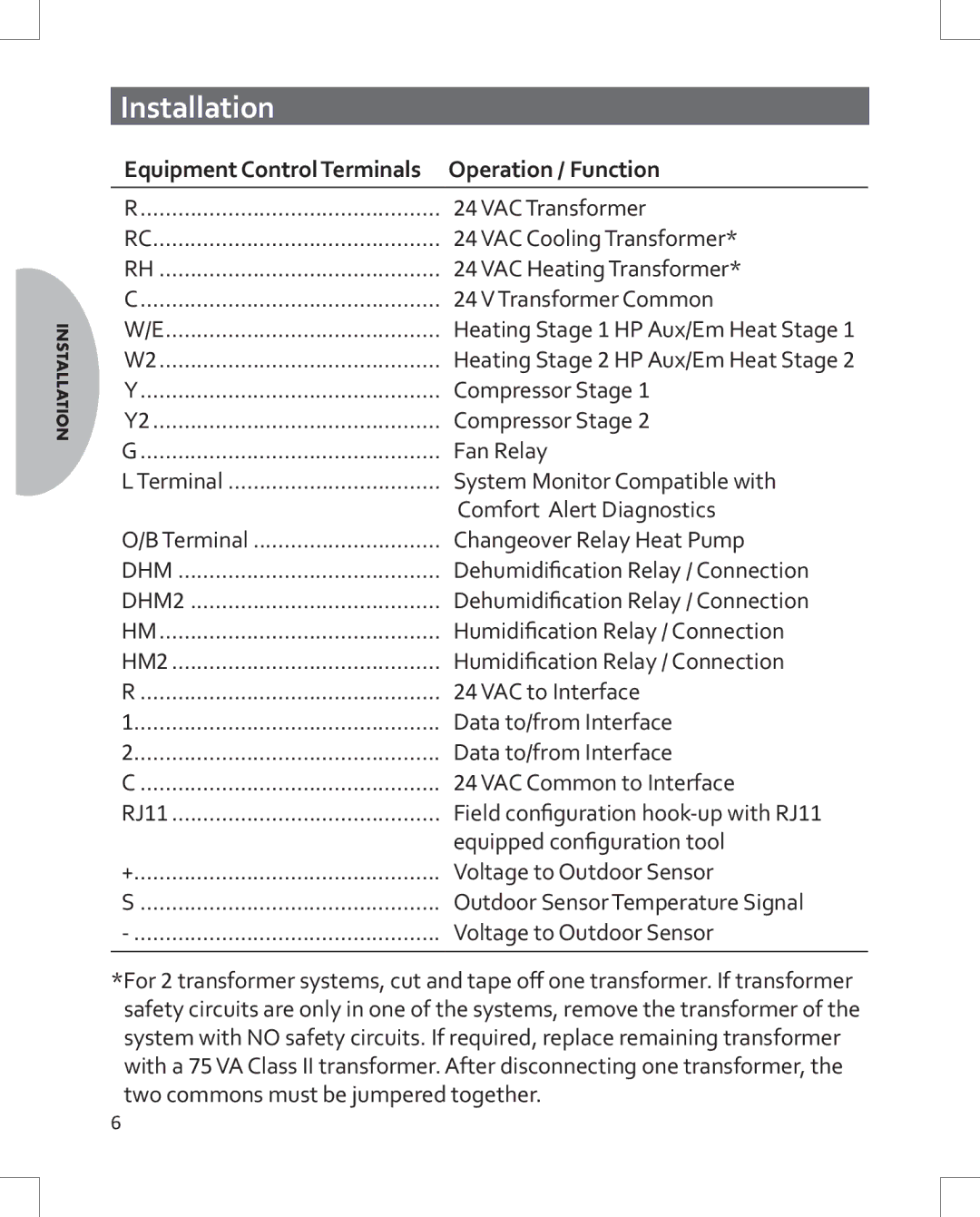
Equipment Control Terminals | Operation / Function |
|
|
R | 24 VAC Transformer |
RC | 24 VAC Cooling Transformer* |
RH | 24 VAC Heating Transformer* |
C | 24 V Transformer Common |
W/E | Heating Stage 1 HP Aux/Em Heat Stage 1 |
W2 | Heating Stage 2 HP Aux/Em Heat Stage 2 |
Y | Compressor Stage 1 |
Y2 | Compressor Stage 2 |
G | Fan Relay |
L Terminal | System Monitor Compatible with |
| Comfort Alert Diagnostics |
O/B Terminal | Changeover Relay Heat Pump |
DHM | Dehumidification Relay / Connection |
DHM2 | Dehumidification Relay / Connection |
HM | Humidification Relay / Connection |
HM2 | Humidification Relay / Connection |
R | 24 VAC to Interface |
1 | Data to/from Interface |
2 | Data to/from Interface |
C | 24 VAC Common to Interface |
RJ11 | Field configuration |
| equipped configuration tool |
+ | Voltage to Outdoor Sensor |
S | Outdoor Sensor Temperature Signal |
Voltage to Outdoor Sensor | |
|
|
*For 2 transformer systems, cut and tape off one transformer. If transformer safety circuits are only in one of the systems, remove the transformer of the system with NO safety circuits. If required, replace remaining transformer with a 75 VA Class II transformer. After disconnecting one transformer, the two commons must be jumpered together.
6