Installation
2.3.2Connecting to External Panel Boards
The following instructions are also shipped attached to the rear of the unit.
INPUT CABLING AND PROTECTION
Table Below Applies to
UPS equipped with a Maintenance Bypass Cabinet (Without Transformer)
| Input Voltage – 208VAC | Input Voltage – 240VAC | |||
| Max. Current | Recommended | Max. Current |
| Recommended |
Max. System | Input Protection |
| Input Protection | ||
in UPS mode | in UPS mode |
| |||
Load Rating | Circuit Breaker |
| Circuit Breaker | ||
|
|
| |||
|
|
|
|
|
|
12kVA | 53 amps | 75 amps | 46 amps |
| 75 amps |
|
|
|
|
|
|
16kVA | 70 amps | 100 amps | 62 amps |
| 100 amps |
|
|
|
|
|
|
20kVA | 102 amps | 125 amps* | 88 amps |
| 125 amps* |
|
|
|
|
|
|
Terminal |
| Maximum: 35mm2 (2AWG) | * Must use 90° copper | wire |
|
Block |
| Minimum: 16mm2 (6AWG) |
| ||
Details |
| Torque Rating: |
| ||
|
|
|
|
|
|
UPS With Maintenance Bypass Cabinet (With Transformer)
Single Input Feed: All UPS ratings must use 125A input circuit breaker protection.
Dual Input Feed: See table below.
|
|
| UPS Feed |
| Bypass Feed | ||
|
|
|
|
| |||
| Input Voltage – 208VAC | Input Voltage – 240VAC | 208V or 240V | ||||
|
|
|
|
|
|
| |
Max. System | Max. Current | Recommended | Max. Current |
| Recommended Input | Recommended | |
Input Protection |
| Input Protection | |||||
Load Rating | in UPS mode | Circuit Breaker | in UPS mode |
| Protection Circuit Breaker | Circuit Breaker | |
12kVA | 53 amps | 75 amps | 46 amps |
| 75 amps | 125 amps* | |
|
|
|
|
|
|
| |
16kVA | 70 amps | 100 amps | 62 amps |
| 100 amps | 125 amps* | |
|
|
|
|
|
|
| |
20kVA | 102 amps | 125 amps* | 88 amps |
| 125 amps* | 125 amps* | |
|
|
|
|
|
| ||
Terminal |
| Maximum: | 35mm2 (2AWG) | * Must use 90° copper wire |
| ||
Block |
|
| Minimum: 16mm2 (6AWG) |
| |||
Details |
| Torque Rating: |
| ||||
|
|
|
|
|
| ||
|
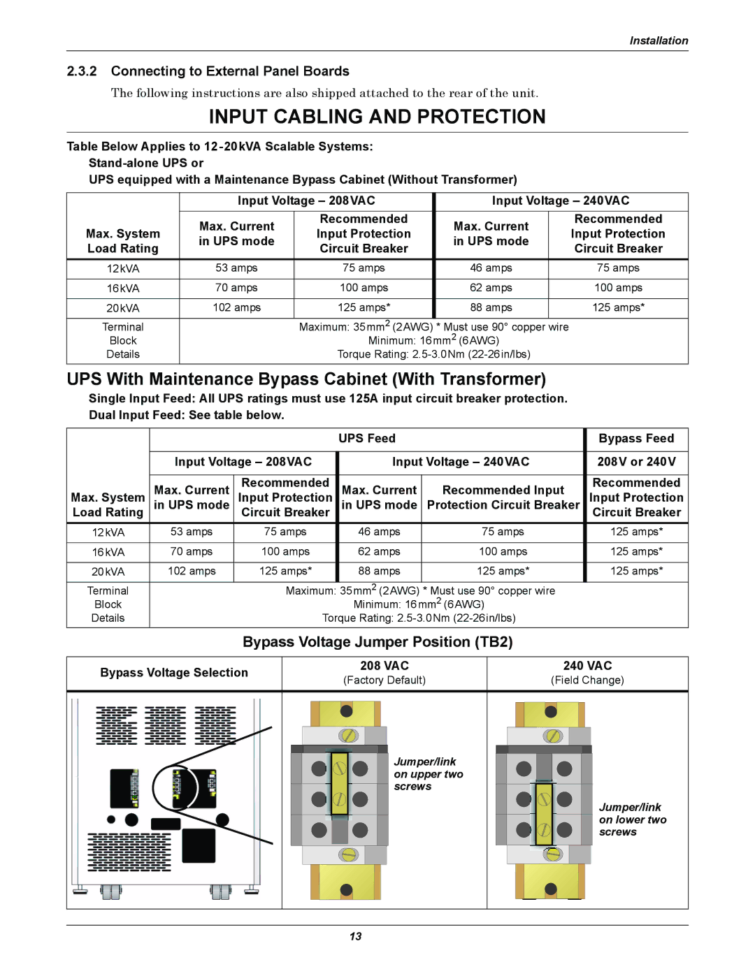
| Bypass Voltage Jumper Position (TB2) |
| ||||
|
|
|
|
| |||
Bypass Voltage Selection | 208 VAC | 240 VAC | |||||
(Factory Default) | (Field Change) | ||||||
|
|
| |||||
Jumper/link on upper two screws
Jumper/link on lower two screws
13