BYPASSING & ISOLATING (continued)
TRANSFER SWITCH REMOVAL
This procedure explains how to remove the Transfer Switch for inspection and maintenance.
1.Bypass and Isolate the Automatic Transfer Switch by carefully following directions on page
Hazardous voltage capable of causing
electrical shock, burns, or death.
Do not touch isolation contact fingers.
2.Open the ATS cabinet doors all the way. Remove the bottom louvered enclosure pan.
3.Separate the
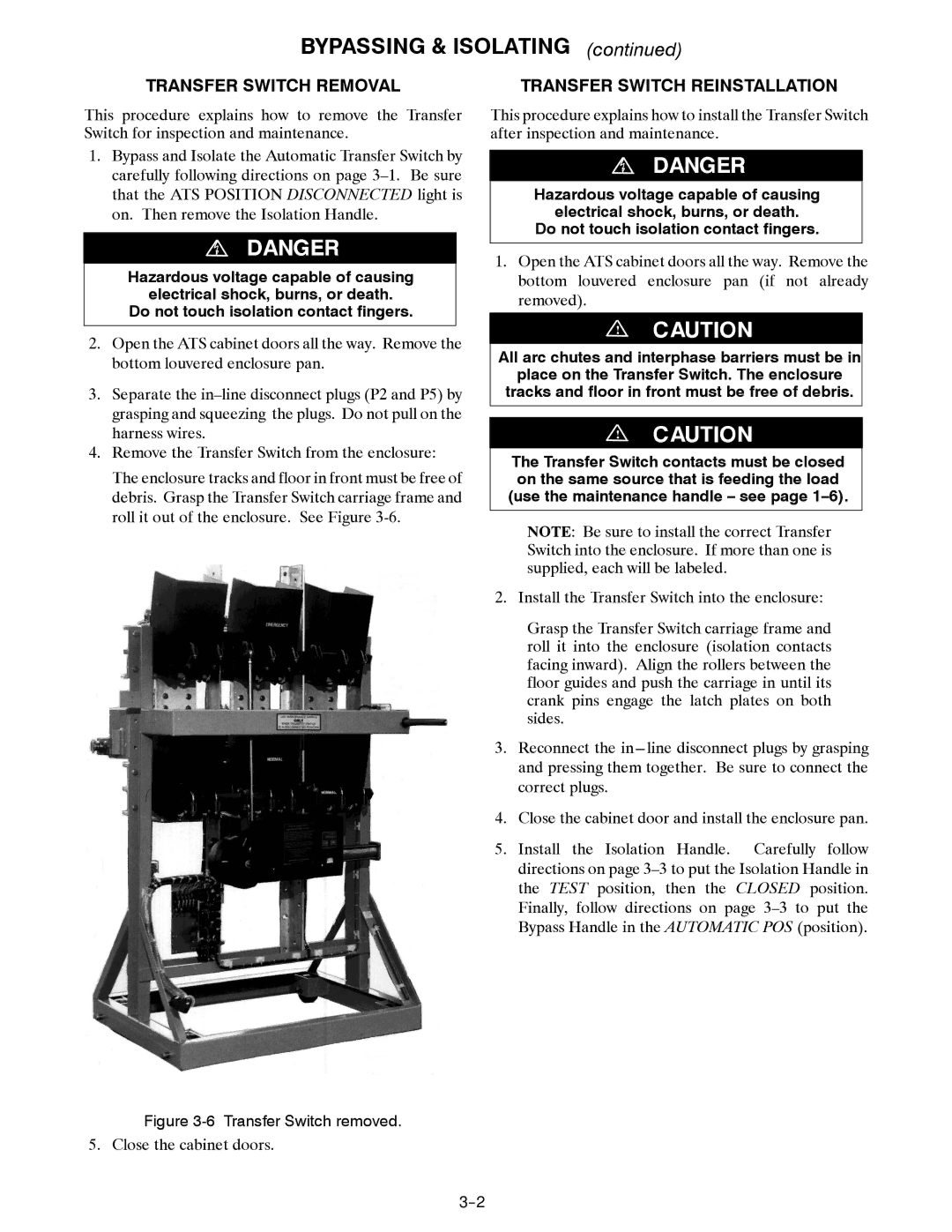
4.Remove the Transfer Switch from the enclosure:
The enclosure tracks and floor in front must be free of debris. Grasp the Transfer Switch carriage frame and roll it out of the enclosure. See Figure
TRANSFER SWITCH REINSTALLATION
This procedure explains how to install the Transfer Switch after inspection and maintenance.
Hazardous voltage capable of causing
electrical shock, burns, or death.
Do not touch isolation contact fingers.
1.Open the ATS cabinet doors all the way. Remove the bottom louvered enclosure pan (if not already removed).
!
All arc chutes and interphase barriers must be in
place on the Transfer Switch. The enclosure tracks and floor in front must be free of debris.
!
The Transfer Switch contacts must be closed on the same source that is feeding the load (use the maintenance handle – see page
NOTE: Be sure to install the correct Transfer Switch into the enclosure. If more than one is supplied, each will be labeled.
2. Install the Transfer Switch into the enclosure:
Grasp the Transfer Switch carriage frame and roll it into the enclosure (isolation contacts facing inward). Align the rollers between the floor guides and push the carriage in until its crank pins engage the latch plates on both sides.
3.Reconnect the
4.Close the cabinet door and install the enclosure pan.
5.Install the Isolation Handle. Carefully follow directions on page
Figure 3-6 Transfer Switch removed.
5. Close the cabinet doors.