INSTALLATION (continued)
Connecting Power Conductors
A Wiring Diagram is furnished with the ATB. All wiring must be made in accordance with the local codes. After the power cables have been tested, connect them to the appropriate terminal lugs on the Bypass Switch as shown on the wiring diagram provided with this ATB. Make sure that the lugs provided are suitable for use with the cables being installed. Standard terminal lugs are solderless screw type and will accept the wire sizes listed on the drawings provided with the ATB. Be careful when stripping insulation from conductors; avoid nicking or ringing the conductor. Remove surface oxides from conductors by cleaning with a wire brush. Follow conductor manufacturer’s instructions when aluminum conductor is used. Apply joint compound to conductor, then carefully wipe away excess compound. Tighten the cable lugs to the torque specified on the rating label.
!
Be sure that the Normal and Emergency power
connections are in proper phase rotation.
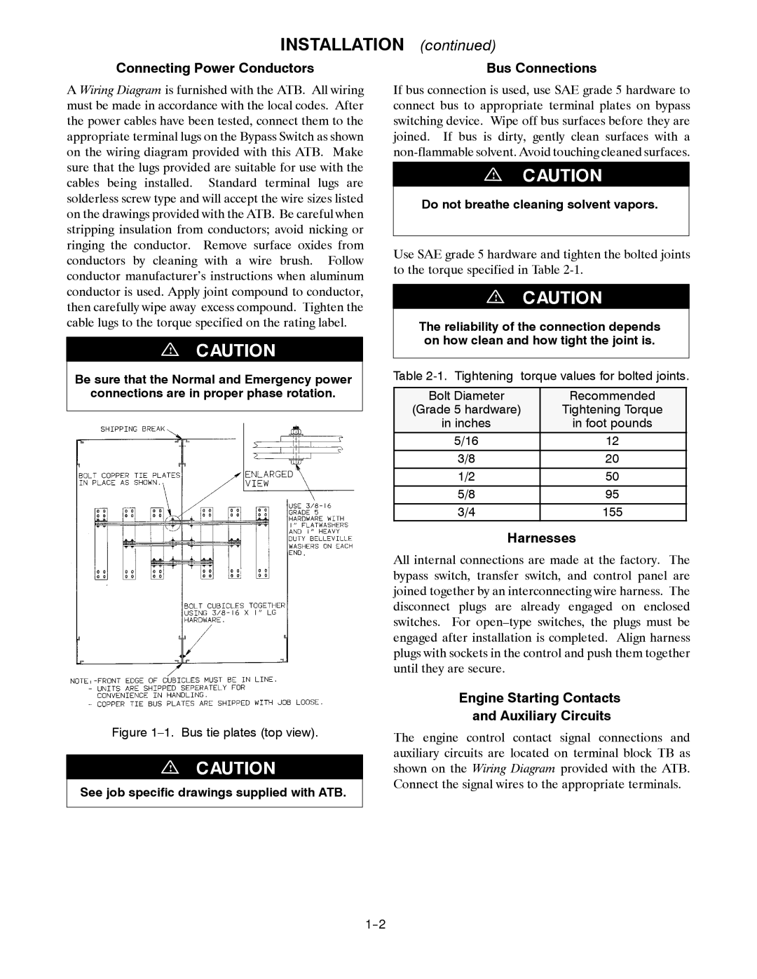
Figure 1–1. Bus tie plates (top view).
!
See job specific drawings supplied with ATB.
Bus Connections
If bus connection is used, use SAE grade 5 hardware to connect bus to appropriate terminal plates on bypass switching device. Wipe off bus surfaces before they are joined. If bus is dirty, gently clean surfaces with a
!
Do not breathe cleaning solvent vapors.
Use SAE grade 5 hardware and tighten the bolted joints to the torque specified in Table
!
The reliability of the connection depends on how clean and how tight the joint is.
Table
Bolt Diameter | Recommended |
(Grade 5 hardware) | Tightening Torque |
in inches | in foot pounds |
5/16 | 12 |
3/8 | 20 |
1/2 | 50 |
5/8 | 95 |
3/4 | 155 |
Harnesses
All internal connections are made at the factory. The bypass switch, transfer switch, and control panel are joined together by an interconnecting wire harness. The disconnect plugs are already engaged on enclosed switches. For
Engine Starting Contacts
and Auxiliary Circuits
The engine control contact signal connections and auxiliary circuits are located on terminal block TB as shown on the Wiring Diagram provided with the ATB. Connect the signal wires to the appropriate terminals.