INSTALLATION (continued)
2 – Manual Operation Test
This procedure will check the manual operation of the Bypass Switch, Isolation Switch, and Transfer Switch. Observe the lights on the Status Indicator panel. The Bypass Switch CLOSED ON NORMAL and the TEST lights should be on. See Figure
1.Isolate the Automatic Transfer Switch:
Install the Isolation Handle and turn it counterclock- wise until it stops (approximately 7 or 8 turns). The Automatic Transfer Switch is now in the Discon- nected position (See Figure
The DISCONNECTED light should come on.
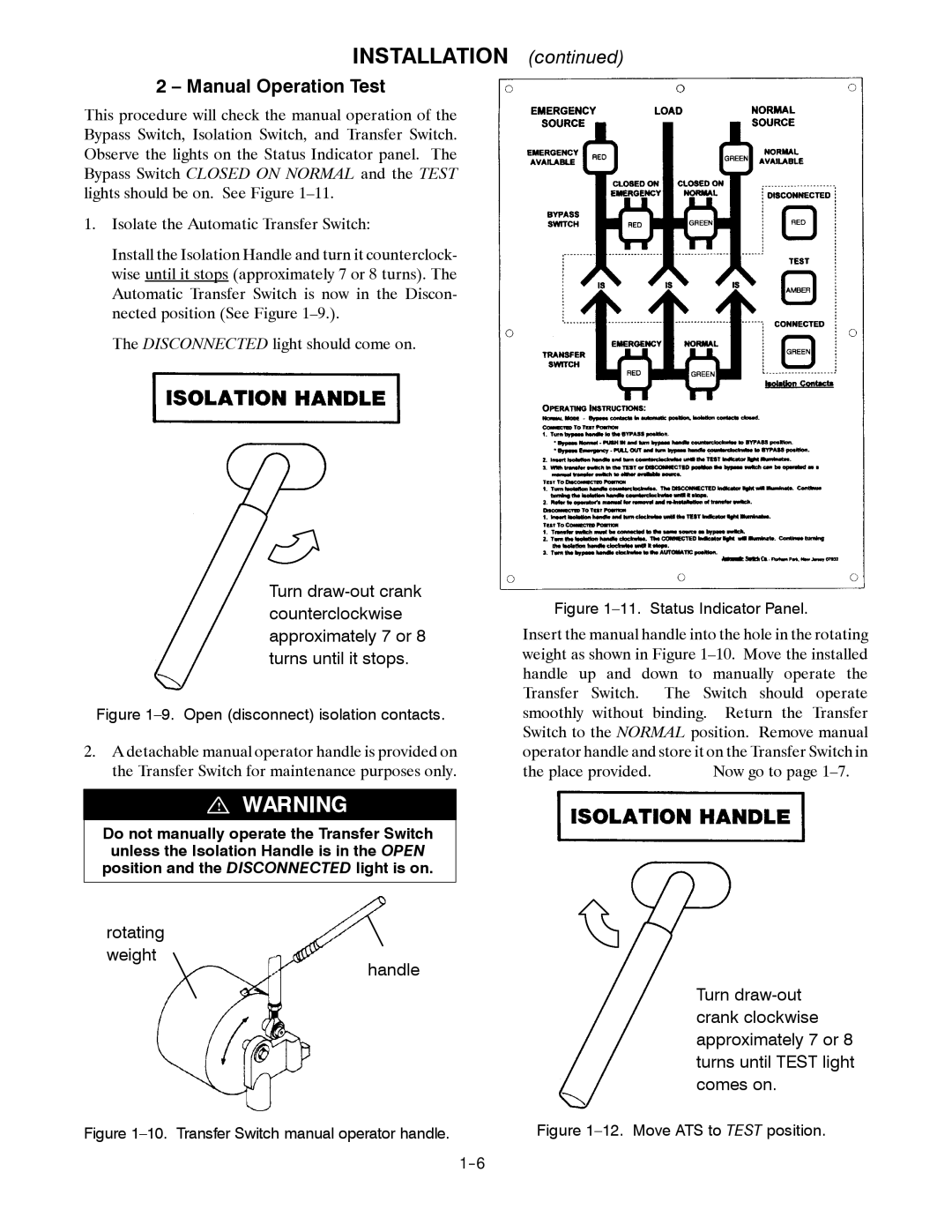
Turn
Figure 1–9. Open (disconnect) isolation contacts.
2.A detachable manual operator handle is provided on the Transfer Switch for maintenance purposes only.
!
Do not manually operate the Transfer Switch unless the Isolation Handle is in the OPEN position and the DISCONNECTED light is on.
rotating
weight
handle
Figure 1–10. Transfer Switch manual operator handle.
Figure 1–11. Status Indicator Panel.
Insert the manual handle into the hole in the rotating weight as shown in Figure
the place provided. | Now go to page |
Turn