INSTALLATION (continued)
Inspection 1
!
Do not force the Isolation Handle. Be sure that the sensing lead isolation contacts do not hit the male stabs head on, but rather slide on them.
|
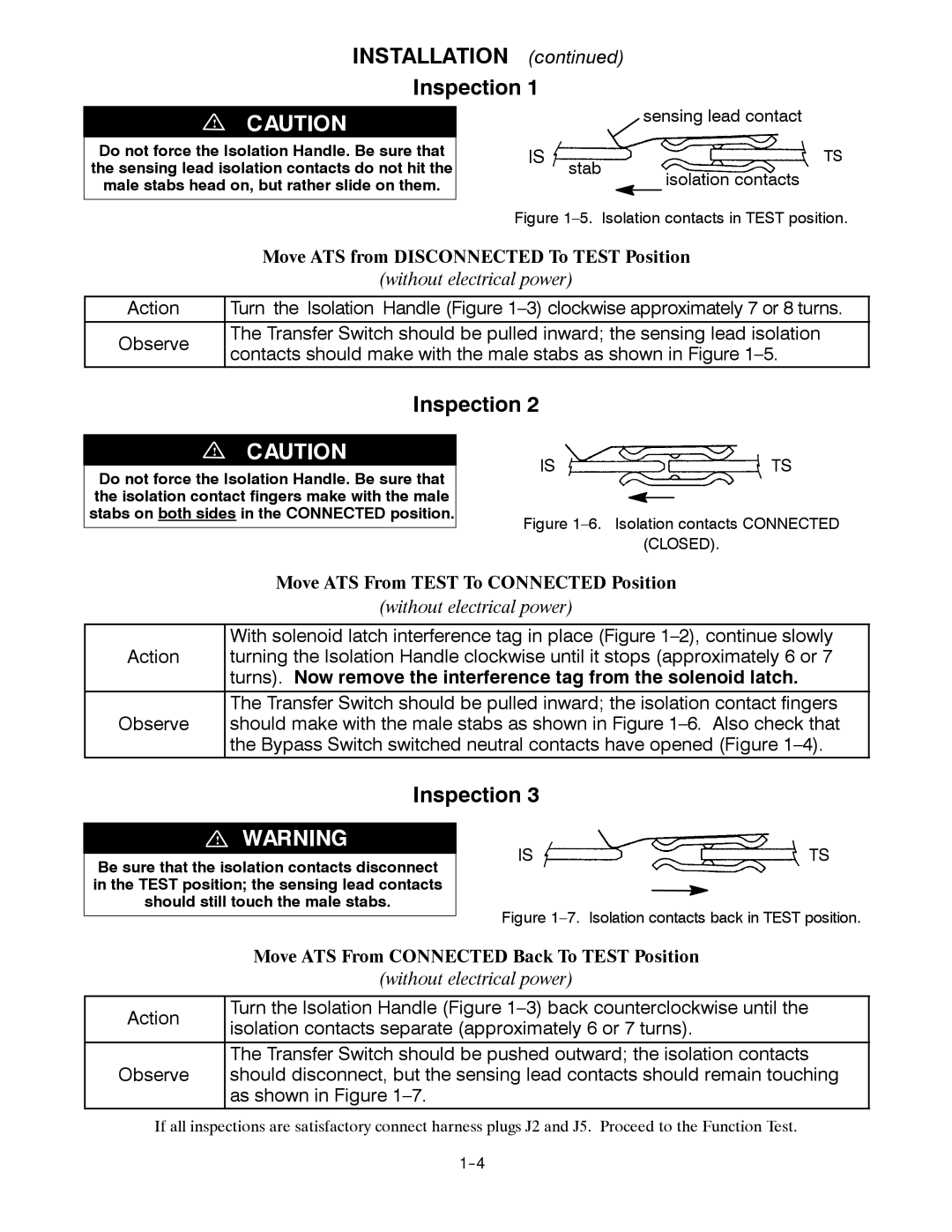
| sensing lead contact | |
IS | stab |
| TS |
|
| isolation contacts | |
|
|
| |
Figure 1–5. Isolation contacts in TEST position.
| Move ATS from DISCONNECTED To TEST Position | |
| (without electrical power) | |
|
| |
Action | Turn the Isolation Handle (Figure | |
Observe | The Transfer Switch should be pulled inward; the sensing lead isolation | |
contacts should make with the male stabs as shown in Figure | ||
| ||
| Inspection 2 |
!
Do not force the Isolation Handle. Be sure that the isolation contact fingers make with the male stabs on both sides in the CONNECTED position.
IS ![]() TS
TS
Figure 1–6. Isolation contacts CONNECTED
(CLOSED).
Move ATS From TEST To CONNECTED Position
(without electrical power)
With solenoid latch interference tag in place (Figure
Action turning the Isolation Handle clockwise until it stops (approximately 6 or 7 turns). Now remove the interference tag from the solenoid latch.
The Transfer Switch should be pulled inward; the isolation contact fingers
Observe should make with the male stabs as shown in Figure
Inspection 3
!
Be sure that the isolation contacts disconnect in the TEST position; the sensing lead contacts should still touch the male stabs.
IS ![]() TS
TS
Figure 1–7. Isolation contacts back in TEST position.
| Move ATS From CONNECTED Back To TEST Position | |
| (without electrical power) | |
|
| |
Action | Turn the Isolation Handle (Figure | |
isolation contacts separate (approximately 6 or 7 turns). | ||
| ||
| The Transfer Switch should be pushed outward; the isolation contacts | |
Observe | should disconnect, but the sensing lead contacts should remain touching | |
| as shown in Figure |
If all inspections are satisfactory connect harness plugs J2 and J5. Proceed to the Function Test.