INSTALLATION (continued)
Install the Transfer Switch
After the enclosure is installed and power cables or bus connected to the Bypass Switch, the Transfer Switch carriage can be rolled in. The floor of the cabinet must be free of debris and clean. If necessary, use a vacuum cleaner. Make a thorough inspection to be sure no tools are left inside. The Bypass Handle must be in the BYPASS POS position (closed on normal). The Isolation Handle (draw- out crank) must be fully counterclockwise against stop.
Do not apply any electrical power to the ATB yet.
It is not necessary to remove the barriers from the bypass switch and transfer switch. If you do remove them, however, reinstall them carefully.
NOTE: Be sure to roll the correct Transfer Switch into the enclosure. If more than one is supplied, each will be labeled above the solenoid operator.
The Transfer Switch NORMAL contacts must be closed. If not, use the manual operator handle (maintenance handle stored on lower carriage) to manually operate the switch. See Figure
NOTE: Solenoid lock SL1 on the Isolation shaft inhibits operation of the drawout (Isola- tion contacts) unless the Transfer Switch and Bypass Switch are in compatible positions. This solenoid must energize to unlock. Be- cause all power sources are
Do the three inspections on page
!
Do not apply any power to the Bypass Switch. Be sure that the Normal and Emergency source circuit breakers are OPEN before proceeding.
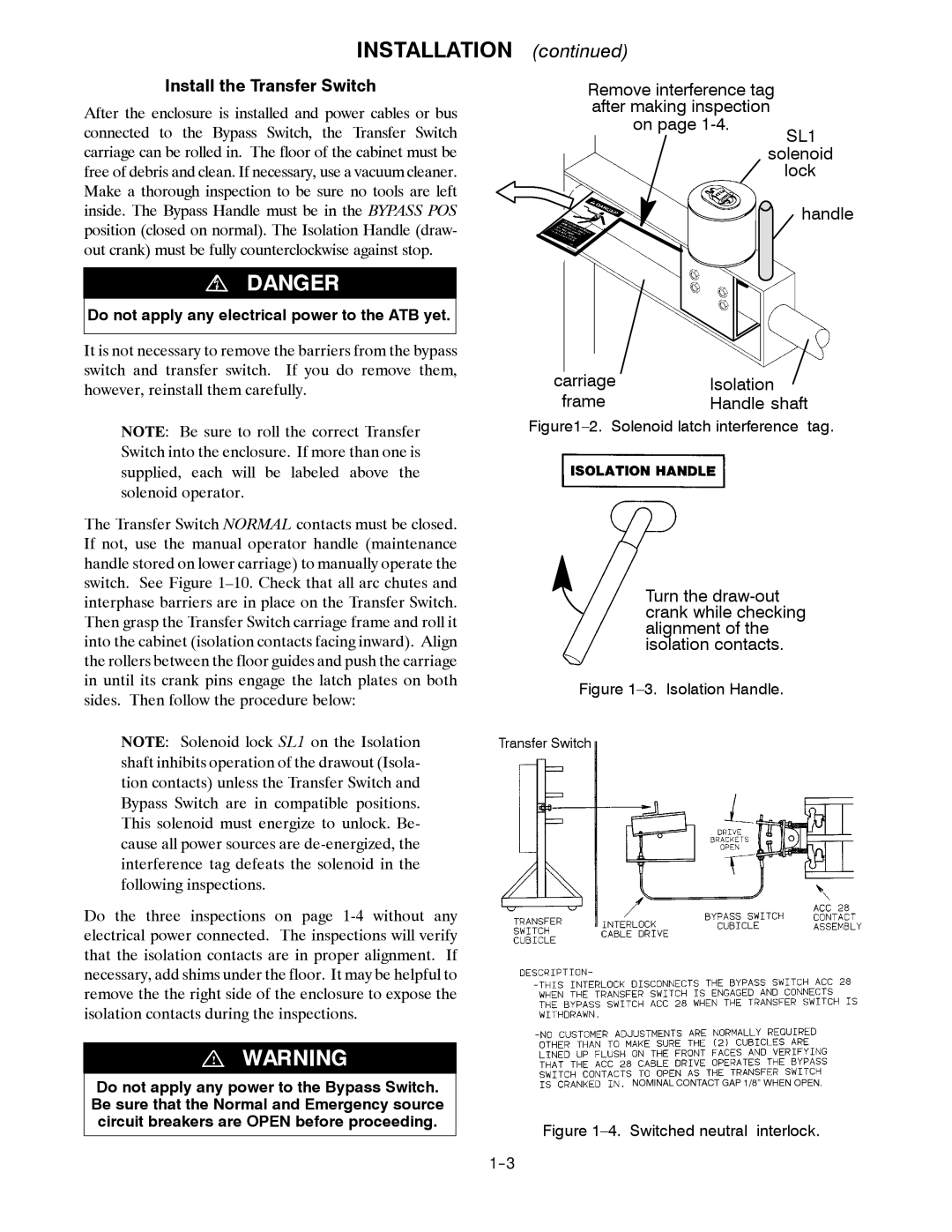
Remove interference tag after making inspection
on page
lock
handle
carriage | Isolation |
frame | Handle shaft |
Figure1–2. Solenoid latch interference tag.
Turn the
Figure 1–3. Isolation Handle.
Transfer Switch
NOMINAL CONTACT GAP 1/8” WHEN OPEN.