! WARNING
It is critical that the pin in the hanger ball is properly installed and the setscrew securely tightened. Failure to verify that the pin and setscrew are properly installed could result in the fan falling.
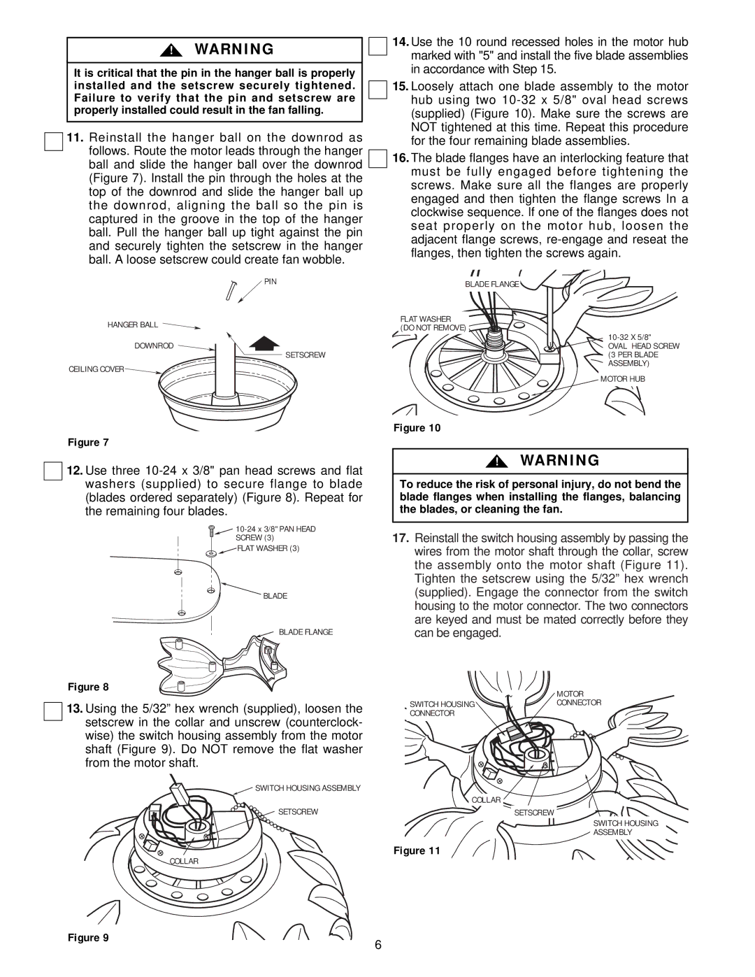
11.Reinstall the hanger ball on the downrod as follows. Route the motor leads through the hanger ball and slide the hanger ball over the downrod (Figure 7). Install the pin through the holes at the top of the downrod and slide the hanger ball up the downrod, aligning the ball so the pin is captured in the groove in the top of the hanger ball. Pull the hanger ball up tight against the pin and securely tighten the setscrew in the hanger ball. A loose setscrew could create fan wobble.
 PIN
PIN
HANGER BALL
DOWNROD
SETSCREW
CEILING COVER 
Figure 7
12.Use three
![]()
![]()
SCREW (3)
![]() FLAT WASHER (3)
FLAT WASHER (3)
BLADE
BLADE FLANGE
Figure 8
13.Using the 5/32” hex wrench (supplied), loosen the setscrew in the collar and unscrew (counterclock- wise) the switch housing assembly from the motor shaft (Figure 9). Do NOT remove the flat washer from the motor shaft.
![]() SWITCH HOUSING ASSEMBLY
SWITCH HOUSING ASSEMBLY
SETSCREW
COLLAR
14.Use the 10 round recessed holes in the motor hub marked with "5" and install the five blade assemblies in accordance with Step 15.
15.Loosely attach one blade assembly to the motor hub using two
16.The blade flanges have an interlocking feature that must be fully engaged before tightening the screws. Make sure all the flanges are properly engaged and then tighten the flange screws In a clockwise sequence. If one of the flanges does not seat properly on the motor hub, loosen the adjacent flange screws,
BLADE FLANGE
FLAT WASHER (DO NOT REMOVE)
OVAL HEAD SCREW (3 PER BLADE ASSEMBLY)
MOTOR HUB
Figure 10
!WARNING
To reduce the risk of personal injury, do not bend the blade flanges when installing the flanges, balancing the blades, or cleaning the fan.
17.Reinstall the switch housing assembly by passing the wires from the motor shaft through the collar, screw the assembly onto the motor shaft (Figure 11). Tighten the setscrew using the 5/32” hex wrench (supplied). Engage the connector from the switch housing to the motor connector. The two connectors are keyed and must be mated correctly before they can be engaged.
| MOTOR |
SWITCH HOUSING | CONNECTOR |
CONNECTOR |
|
COLLAR
SETSCREW
SWITCH HOUSING
ASSEMBLY
Figure 11
Figure 9
6
