CF820ORB00, CF820PW00 specifications
The Emerson CF820ORB00 and CF820PW00 ceiling fans are part of a distinguished line known for their aesthetic appeal and functional efficiency, designed to enhance both comfort and style in various living spaces. With a focus on modern design, these fans are perfect for contemporary homes while still offering a touch of elegance.One of the main features of the CF820 series is its exceptional airflow efficiency, making it an ideal choice for rooms of varying sizes. Both models are equipped with high-performance motors that deliver powerful air circulation, ensuring that any space remains cool and comfortable throughout the year. The fans also operate quietly, allowing for a peaceful environment whether you're sleeping, working, or enjoying leisure time.
The Emerson CF820ORB00 is designed with an oil-rubbed bronze finish that complements a variety of interior aesthetics. Its sleek blades ensure a clean and simple look, making it a versatile choice for many home styles. The fan’s 52-inch blade span is perfect for larger rooms, efficiently circulating air without overwhelming the space.
In contrast, the CF820PW00 features a pristine white finish that blends seamlessly with lighter interior themes. This model also boasts a comparable 52-inch blade span while emphasizing a more minimalist design, ideal for modern or coastal-themed settings. Both fans enhance the overall décor of your living space while providing optimal functionality.
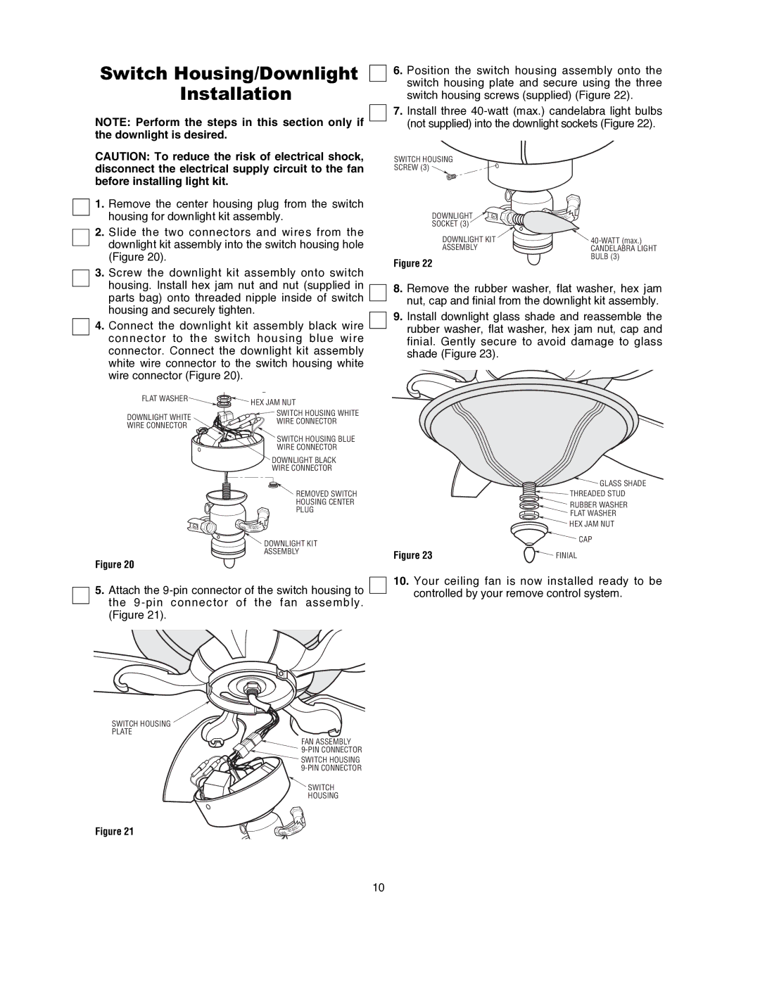
Technology is another key aspect where the Emerson CF820 series shines. These fans often come equipped with the Emerson Premium Energy Star rated fan motors, which ensure energy efficiency and reduced electricity costs. The inclusion of a remote control allows users to adjust the fan speeds conveniently without leaving the comfort of their seats. Some models may offer integrated lighting options, giving homeowners an additional source of illumination, further enhancing the fan's practicality and charm.
The fans are compatible with various mounting options, allowing for both standard and angled installations. This versatility ensures that they can fit in diverse environments, whether it's a spacious living room, a cozy bedroom, or a stylish outdoor patio.
Overall, the Emerson CF820ORB00 and CF820PW00 ceiling fans exemplify a harmonious blend of performance and design. Their sophisticated styling, energy-efficient technologies, and adaptability make them a wise and stylish choice for homeowners looking to enhance their spaces. Whether you're searching for functionality or a decorative accent, these ceiling fans deliver exceptional quality and impressive performance.

