Wiring
Figure 16 Applying the heat shrink
g.Position gland clamping insert so the interior end is flush with the heat shrink.
h.Fold the cloth shield or braid and drain wires over the clamping insert and approximately 1/8 inch (3 mm) past the
Figure 17 Folding the cloth shield
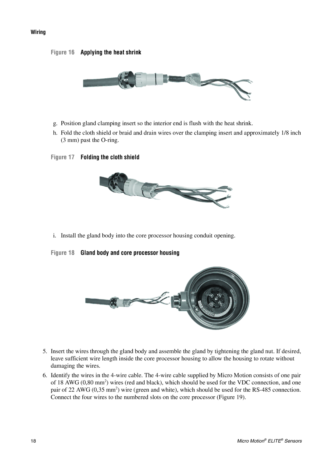
i. Install the gland body into the core processor housing conduit opening.
Figure 18 Gland body and core processor housing
5.Insert the wires through the gland body and assemble the gland by tightening the gland nut. If desired, leave sufficient wire length inside the core processor housing to allow the housing to rotate without damaging the wires.
6.Identify the wires in the
18 | Micro Motion® ELITE® Sensors |