Determining a Location
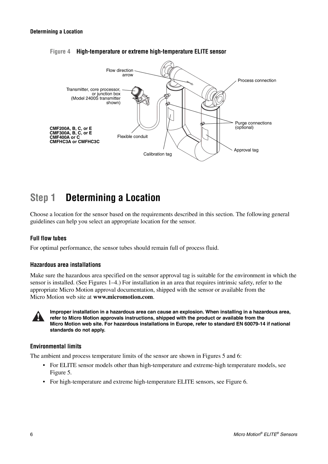
Figure 4 High-temperature or extreme high-temperature ELITE sensor
Flow direction arrow
Process connection
Transmitter, core processor, ![]() or junction box
or junction box
(Model 2400S transmitter shown)
CMF200A, B, C, or E CMF300A, B, C, or E CMF400A or C CMFHC3A or CMFHC3C
![]() Purge connections (optional)
Purge connections (optional)
Flexible conduit
Approval tag
Calibration tag
Step 1 Determining a Location
Choose a location for the sensor based on the requirements described in this section. The following general guidelines can help you select an appropriate location for the sensor.
Full flow tubes
For optimal performance, the sensor tubes should remain full of process fluid.
Hazardous area installations
Make sure the hazardous area specified on the sensor approval tag is suitable for the environment in which the sensor is installed. (See Figures
Micro Motion web site at www.micromotion.com.
Improper installation in a hazardous area can cause an explosion. When installing in a hazardous area, refer to Micro Motion approvals instructions, shipped with the product or available from the
Micro Motion web site. For hazardous installations in Europe, refer to standard EN
Environmental limits
The ambient and process temperature limits of the sensor are shown in Figures 5 and 6:
•For ELITE sensor models other than
•For
6 | Micro Motion® ELITE® Sensors |
